Lexus ES: Outside Handle Foot Light Circuit
DESCRIPTION
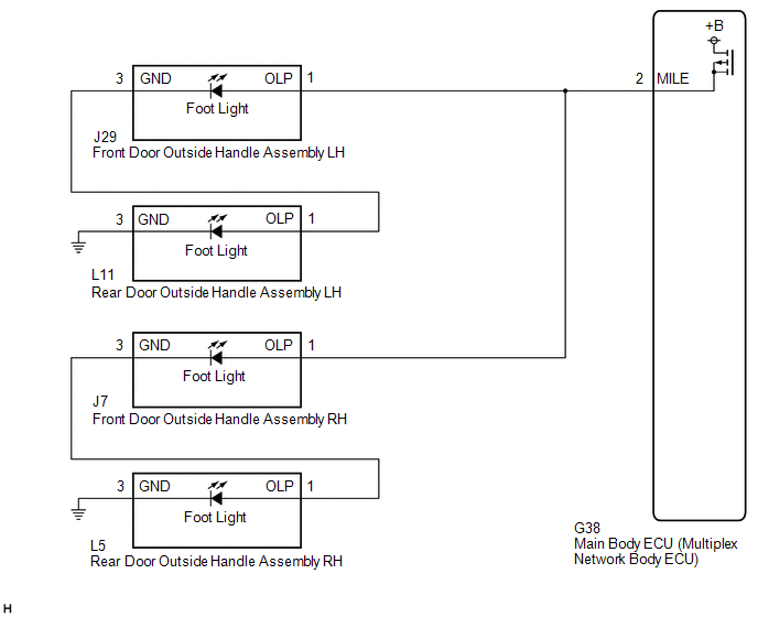
The main body ECU (multiplex network body ECU) controls the outside handle foot lights.
WIRING DIAGRAM
CAUTION / NOTICE / HINT
NOTICE:
Before replacing the main body ECU (multiplex network body ECU), refer to Registration.
Click here .gif)
PROCEDURE
| 1. | PERFORM ACTIVE TEST USING TECHSTREAM |
(a) Connect the Techstream to the DLC3.
(b) Turn the engine switch on (IG).
(c) Turn the Techstream on.
(d) Enter the following menus: Body Electrical / Main Body / Active Test.
(e) Perform the Active Test according to the display on the Techstream.
Body Electrical > Main Body > Active Test| Tester Display | Measurement Item | Control Range | Diagnostic Note |
|---|---|---|---|
| Exterior Light | Outside handle foot lights | OFF or ON | - |
| Tester Display |
|---|
| Exterior Light |
OK:
Outside handle foot lights illuminate.
| OK | .gif) | PROCEED TO NEXT SUSPECTED AREA SHOWN IN PROBLEM SYMPTOMS TABLE |
|
.gif)
| 2. | CHECK HARNESS AND CONNECTOR (FRONT DOOR OUTSIDE HANDLE ASSEMBLY LH - MAIN BODY ECU (MULTIPLEX NETWORK BODY ECU)) |
(a) Disconnect the J29 front door outside handle assembly LH connector.
(b) Disconnect the J7 front door outside handle assembly RH connector.
(c) Disconnect the G38 main body ECU (multiplex network body ECU) connector.
(d) Measure the resistance according to the value(s) in the table below.
Standard Resistance:
| Tester Connection | Condition | Specified Condition |
|---|---|---|
| J29-1 (OLP) - G38-2 (MILE) | Always | Below 1 Ω |
| J29-1 (OLP) or G38-2 (MILE) - Body ground | Always | 10 kΩ or higher |
| OK | | REPLACE MAIN BODY ECU (MULTIPLEX NETWORK BODY ECU) |
| NG | | REPAIR OR REPLACE HARNESS OR CONNECTOR |
READ NEXT:
 Front Side Marker Light Circuit
DESCRIPTION When the light control switch is in the tail or head position, the main body ECU (multiplex network body ECU) sends an illumination request signal to the headlight ECU sub-assembly to illu
Taillight Relay Circuit
DESCRIPTION The main body ECU (multiplex network body ECU) controls the operation of the TAIL relay. WIRING DIAGRAM CAUTION / NOTICE / HINT NOTICE:
Inspect the fuses for circuits related to this s
Cornering Light Circuit
DESCRIPTION The headlight ECU sub-assembly controls the cornering lights. WIRING DIAGRAM except Bulb Type Turn Signal Light (for TMMK Made) for Bulb Type Turn Signal Light (for TMMK Made) CAUTION /
SEE MORE:
Precaution
PRECAUTION PRECAUTION FOR DISCONNECTING CABLE FROM NEGATIVE BATTERY TERMINAL NOTICE: When disconnecting the cable from the negative (-) battery terminal, initialize the following systems after the cable is reconnected. System Name See Procedure Lane Control System (for Gasoline Model)
Definition Of Terms
DEFINITION OF TERMS Term Definition Monitor Description Description of what the battery ECU assembly monitors and how to detects malfunctions (monitoring purpose and its details). Related DTCs A group of diagnostic trouble codes that are output by the battery ECU assembly based on t
