Lexus ES: Front Side Marker Light Circuit
DESCRIPTION
When the light control switch is in the tail or head position, the main body ECU (multiplex network body ECU) sends an illumination request signal to the headlight ECU sub-assembly to illuminate the front side marker lights.
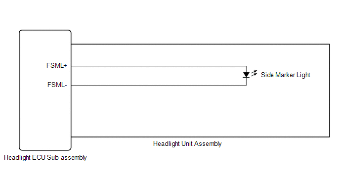
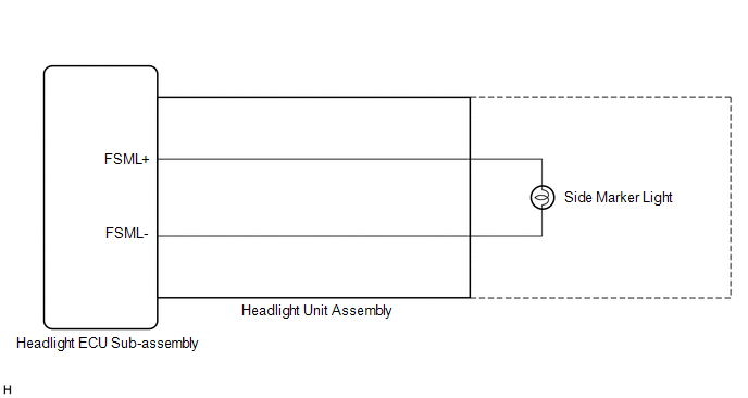
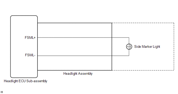
WIRING DIAGRAM
for LED Type Turn Signal Light
for Bulb Type Turn Signal Light (for TMC Made)
for Bulb Type Turn Signal Light (for TMMK Made)
CAUTION / NOTICE / HINT
NOTICE:
-
If the headlight ECU sub-assembly LH has been replaced, it is necessary to synchronize the vehicle information and initialize the headlight ECU sub-assembly LH.*1
Click here
.gif)
-
If the headlight ECU sub-assembly LH has been replaced, it is necessary to synchronize the vehicle information the headlight ECU sub-assembly LH.*2
Click here
-
If the headlight assembly LH has been replaced, it is necessary to synchronize the vehicle information the headlight ECU sub-assembly LH.*3
Click here
- Inspect the front side marker light bulb before performing the following procedure.*2
-
When replacing the headlight ECU sub-assembly LH, always replace it with a new one. If a headlight ECU sub-assembly LH which was installed to another vehicle is used, the information stored in it will not match the information from the vehicle and a DTC may be stored.
- *1: for LED Type Turn Signal Light
- *2: for Bulb Type Turn Signal Light
- *3: for Bulb Type Turn Signal Light (for TMMK Made)
PROCEDURE
| 1. | CONFIRM MODEL |
(a) Choose the model to be inspected.
| Result | Proceed to |
|---|---|
| for LED Type Turn Signal Light | A |
| for Bulb Type Turn Signal Light | B |
| B | .gif) | GO TO STEP 5 |
|
.gif)
| 2. | CHECK LIGHTS |
(a) Check the illumination of each front side marker lights.
| Result | Proceed to |
|---|---|
| LH side front side marker light does not illuminate | A |
| RH side front side marker light does not illuminate | B |
| B | | GO TO STEP 4 |
|
| 3. | PERFORM ACTIVE TEST USING TECHSTREAM |
(a) Connect the Techstream to the DLC3.
(b) Turn the engine switch on (IG).
(c) Turn the Techstream on.
(d) Enter the following menus: Body Electrical / AFS / Active Test.
(e) Perform the Active Test according to the display on the Techstream.
Body Electrical > AFS > Active Test| Tester Display | Measurement Item | Control Range | Diagnostic Note |
|---|---|---|---|
| Clearance Light | Parking lights | OFF or ON | - |
| Tester Display |
|---|
| Clearance Light |
OK:
Front side marker light illuminate.
| OK | | PROCEED TO NEXT SUSPECTED AREA SHOWN IN PROBLEM SYMPTOMS TABLE |
| NG | | GO TO STEP 9 |
| 4. | PERFORM ACTIVE TEST USING TECHSTREAM |
(a) Connect the Techstream to the DLC3.
(b) Turn the engine switch on (IG).
(c) Turn the Techstream on.
(d) Enter the following menus: Body Electrical / AFS (Sub) / Active Test.
(e) Perform the Active Test according to the display on the Techstream.
Body Electrical > AFS (Sub) > Active Test| Tester Display | Measurement Item | Control Range | Diagnostic Note |
|---|---|---|---|
| Clearance Light | Parking lights | OFF or ON | - |
| Tester Display |
|---|
| Clearance Light |
OK:
Front side marker light illuminate.
| OK | | PROCEED TO NEXT SUSPECTED AREA SHOWN IN PROBLEM SYMPTOMS TABLE |
| NG | | GO TO STEP 16 |
| 5. | CHECK LIGHTS |
(a) Check the illumination of each front side marker lights.
| Result | Proceed to |
|---|---|
| LH side front side marker light does not illuminate | A |
| RH side front side marker light does not illuminate | B |
| B | | GO TO STEP 13 |
|
| 6. | PERFORM ACTIVE TEST USING TECHSTREAM |
(a) Connect the Techstream to the DLC3.
(b) Turn the engine switch on (IG).
(c) Turn the Techstream on.
(d) Enter the following menus: Body Electrical / HL AutoLeveling / Active Test.
(e) Perform the Active Test according to the display on the Techstream.
Body Electrical > HL AutoLeveling > Active Test| Tester Display | Measurement Item | Control Range | Diagnostic Note |
|---|---|---|---|
| Clearance Light | Parking lights | OFF or ON | - |
| Tester Display |
|---|
| Clearance Light |
OK:
Front side marker light illuminate.
| Result | Proceed to |
|---|---|
| OK | A |
| NG (for TMC Made) | B |
| NG (for TMMK Made) | C |
| A | | PROCEED TO NEXT SUSPECTED AREA SHOWN IN PROBLEM SYMPTOMS TABLE |
| C | | GO TO STEP 11 |
|
| 7. | CHECK HEADLIGHT CORD LH |
(a) Interchange the headlight cord LH with RH and connect the connectors.
Click here
|
| 8. | CHECK OPERATION (FRONT SIDE MARKER LIGHT) |
(a) Check that the front side marker light operates normally.
OK:
Front side marker light operates normally.
| NG | | REPLACE HEADLIGHT CORD LH |
|
| 9. | CHECK HEADLIGHT UNIT ASSEMBLY LH |
(a) Interchange the headlight unit assembly LH with RH and connect the connectors.
for LED Type Turn Signal Light: Click here
for Bulb Type Turn Signal Light: Click here
|
| 10. | CHECK OPERATION (FRONT SIDE MARKER LIGHT) |
(a) Check that the front side marker light operates normally.
OK:
Front side marker light operates normally.
| OK | | REPLACE HEADLIGHT ECU SUB-ASSEMBLY LH |
| NG | | REPLACE HEADLIGHT UNIT ASSEMBLY LH |
| 11. | CHECK HEADLIGHT ASSEMBLY LH |
(a) Remove each headlight ECU sub-assembly, interchange the headlight assembly LH with RH and connect the connectors.
Click here
|
| 12. | CHECK OPERATION (FRONT SIDE MARKER LIGHT) |
(a) Check that the front side marker light operates normally.
OK:
Front side marker light operates normally.
| OK | | REPLACE HEADLIGHT ECU SUB-ASSEMBLY LH |
| NG | | REPLACE HEADLIGHT ASSEMBLY LH |
| 13. | PERFORM ACTIVE TEST USING TECHSTREAM |
(a) Connect the Techstream to the DLC3.
(b) Turn the engine switch on (IG).
(c) Turn the Techstream on.
(d) Enter the following menus: Body Electrical / HL AutoLeveling (Sub) / Active Test.
(e) Perform the Active Test according to the display on the Techstream.
Body Electrical > HL AutoLeveling (Sub) > Active Test| Tester Display | Measurement Item | Control Range | Diagnostic Note |
|---|---|---|---|
| Clearance Light | Parking lights | OFF or ON | - |
| Tester Display |
|---|
| Clearance Light |
OK:
Front side marker light illuminate.
| Result | Proceed to |
|---|---|
| OK | A |
| NG (for TMC Made) | B |
| NG (for TMMK Made) | C |
| A | | PROCEED TO NEXT SUSPECTED AREA SHOWN IN PROBLEM SYMPTOMS TABLE |
| C | | GO TO STEP 18 |
|
| 14. | CHECK HEADLIGHT CORD RH |
(a) Interchange the headlight cord RH with LH and connect the connectors.
Click here
|
| 15. | CHECK OPERATION (FRONT SIDE MARKER LIGHT) |
(a) Check that the front side marker light operates normally.
OK:
Front side marker light operates normally.
| NG | | REPLACE HEADLIGHT CORD RH |
|
| 16. | CHECK HEADLIGHT UNIT ASSEMBLY RH |
(a) Interchange the headlight unit assembly RH with LH and connect the connectors.
for LED Type Turn Signal Light: Click here
for Bulb Type Turn Signal Light: Click here
|
| 17. | CHECK OPERATION (FRONT SIDE MARKER LIGHT) |
(a) Check that the front side marker light operates normally.
OK:
Front side marker light operates normally.
| OK | | REPLACE HEADLIGHT ECU SUB-ASSEMBLY RH |
| NG | | REPLACE HEADLIGHT UNIT ASSEMBLY RH |
| 18. | CHECK HEADLIGHT ASSEMBLY RH |
(a) Remove each headlight ECU sub-assembly, interchange the headlight assembly RH with LH and connect the connectors.
Click here
|
| 19. | CHECK OPERATION (FRONT SIDE MARKER LIGHT) |
(a) Check that the front side marker light operates normally.
OK:
Front side marker light operates normally.
| OK | | REPLACE HEADLIGHT ECU SUB-ASSEMBLY RH |
| NG | | REPLACE HEADLIGHT ASSEMBLY RH |
READ NEXT:
 Taillight Relay Circuit
DESCRIPTION The main body ECU (multiplex network body ECU) controls the operation of the TAIL relay. WIRING DIAGRAM CAUTION / NOTICE / HINT NOTICE:
Inspect the fuses for circuits related to this s
Cornering Light Circuit
DESCRIPTION The headlight ECU sub-assembly controls the cornering lights. WIRING DIAGRAM except Bulb Type Turn Signal Light (for TMMK Made) for Bulb Type Turn Signal Light (for TMMK Made) CAUTION /
High Beam Headlight Circuit
DESCRIPTION The headlight ECU sub-assembly controls the high beam headlights. WIRING DIAGRAM except Bulb Type Turn Signal Light (for TMMK Made) for Bulb Type Turn Signal Light (for TMMK Made) CAUTIO
SEE MORE:
Drive Motor "A" Position Sensor Circuit "A" Circuit Voltage Below Threshold (P0C5016,P0C5017,P0C5A16,P0C5A17)
DTC SUMMARY MALFUNCTION DESCRIPTION These DTCs indicate an abnormal resolver output signal. The cause of this malfunction may be one of the following: Internal inverter malfunction
Inverter with converter assembly internal circuit malfunction
Inverter low-voltage circuit malfunction
The con
RCTB Sensor (C1AF7)
DESCRIPTION This DTC is stored when the clearance warning ECU assembly receives a signal from the blind spot monitor system via CAN communication indicating a malfunction in the blind spot monitor sensor. DTC No. Detection Item DTC Detection Condition Trouble Area C1AF7 RCTB Sensor
