Lexus ES: Taillight Relay Circuit
DESCRIPTION
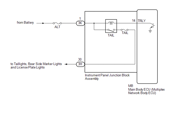
The main body ECU (multiplex network body ECU) controls the operation of the TAIL relay.
WIRING DIAGRAM
CAUTION / NOTICE / HINT
NOTICE:
- Inspect the fuses for circuits related to this system before performing the following procedure.
-
Before replacing the main body ECU (multiplex network body ECU), refer to Registration.
Click here
.gif)
PROCEDURE
| 1. | PERFORM ACTIVE TEST USING TECHSTREAM |
(a) Connect the Techstream to the DLC3.
(b) Turn the engine switch on (IG).
(c) Turn the Techstream on.
(d) Enter the following menus: Body Electrical / Main Body / Active Test.
(e) Perform the Active Test according to the display on the Techstream.
Body Electrical > Main Body > Active Test| Tester Display | Measurement Item | Control Range | Diagnostic Note |
|---|---|---|---|
| Taillight Relay | Taillight relay | OFF or ON | - |
| Tester Display |
|---|
| Taillight Relay |
OK:
Taillights illuminate.
| OK | .gif) | PROCEED TO NEXT SUSPECTED AREA SHOWN IN PROBLEM SYMPTOMS TABLE |
|
.gif)
| 2. | CHECK HARNESS AND CONNECTOR (POWER SOURCE - INSTRUMENT PANEL JUNCTION BLOCK ASSEMBLY) |
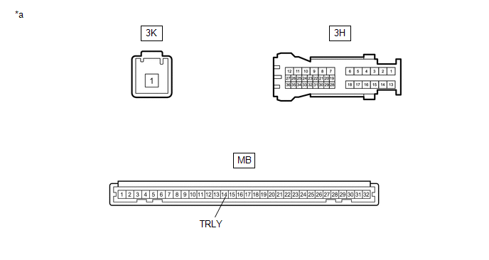
(a) Disconnect the 3K instrument panel junction block assembly connector.
(b) Measure the voltage according to the value(s) in the table below.
Standard Voltage:
| Tester Connection | Condition | Specified Condition |
|---|---|---|
| 3K-1 - Body ground | Always | 11 to 14 V |
| NG | | REPAIR OR REPLACE HARNESS OR CONNECTOR |
|
| 3. | INSPECT INSTRUMENT PANEL JUNCTION BLOCK ASSEMBLY |
| *a | Component without harness connected (Instrument Panel Junction Block Assembly) | - | - |
(a) Remove the main body ECU (multiplex network body ECU) from the instrument panel junction block assembly.
Click here
(b) Connect a positive (+) lead from the battery to terminal 3K-1.
(c) Connect a negative (-) lead from the battery to terminal MB-14 (TRLY).
(d) Measure the voltage according to the value(s) in the table below.
Standard Voltage:
| Tester Connection | Condition | Specified Condition |
|---|---|---|
| 3H-30 - Battery negative (-) terminal | Always | 11 to 14 V |
| OK | | REPLACE MAIN BODY ECU (MULTIPLEX NETWORK BODY ECU) |
| NG | | REPLACE INSTRUMENT PANEL JUNCTION BLOCK ASSEMBLY |
READ NEXT:
 Cornering Light Circuit
DESCRIPTION The headlight ECU sub-assembly controls the cornering lights. WIRING DIAGRAM except Bulb Type Turn Signal Light (for TMMK Made) for Bulb Type Turn Signal Light (for TMMK Made) CAUTION /
High Beam Headlight Circuit
DESCRIPTION The headlight ECU sub-assembly controls the high beam headlights. WIRING DIAGRAM except Bulb Type Turn Signal Light (for TMMK Made) for Bulb Type Turn Signal Light (for TMMK Made) CAUTIO
SEE MORE:
Air Conditioning Amplifier Communication Stop Mode
DESCRIPTION Detection Item Symptom Trouble Area Air Conditioning Amplifier Communication Stop Mode Any of the following conditions are met:
Communication stop for "Air Conditioning Amplifier" is indicated on the "Communication Bus Check" screen of the Techstream.
Click here
Com
Initialization
INITIALIZATION NOTICE:
The necessary procedures (adjustment, calibration, initialization or registration) that must be performed after parts are removed and installed, or replaced during headlight ECU sub-assembly LH removal/installation are shown below. for LED Type Turn Signal Light Replaced
