Lexus ES: On-vehicle Inspection
ON-VEHICLE INSPECTION
CAUTION / NOTICE / HINT
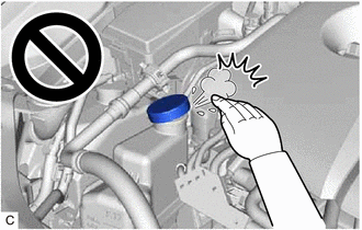
CAUTION:
To avoid the danger of being burned, do not remove the reserve tank cap while the coolant (for inverter) is still hot. Pressurized, hot coolant (for inverter) and steam may be released and cause serious burns.
PROCEDURE
1. INSPECT FOR COOLANT LEAK (for Inverter)
CAUTION:
To avoid the danger of being burned, do not remove the reserve tank cap while the coolant (for inverter) is still hot. Pressurized, hot coolant (for inverter) and steam may be released and cause serious burns.
(a) Remove the reserve tank cap from the inverter reserve tank assembly.
(b) Add coolant to the FULL line of the inverter reserve tank assembly.
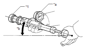
| (c) Install a radiator cap tester to the inverter reserve tank assembly. |
|
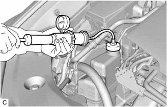
(d) Pump the radiator cap tester to 122 kPa (1.2 kgf/ cm2, 18 psi), and then check that the pressure does not drop.
HINT:
If the pressure drops, check the hoses, radiator assembly, inverter water pump assembly, hybrid vehicle transaxle assembly, and inverter with converter assembly for leaks.
(e) Reinstall the reserve tank cap to the inverter reserve tank assembly.
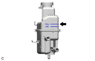
2. INSPECT COOLANT LEVEL IN RESERVE TANK (for Inverter)
| (a) The coolant (for inverter) should be between the LOW and FULL lines when the coolant (for inverter) is cold. HINT: If the coolant level is low, check for leaks and add TOYOTA Super Long Life Coolant (SLLC) or similar high quality ethylene glycol based non-silicate, non-amine, non-nitrite, and non-borate coolant with long-life hybrid organic acid technology up to the FULL line. |
|
3. INSPECT COOLANT QUALITY (for Inverter)
(a) Remove the reserve tank cap from the inverter reserve tank assembly.
CAUTION:
To avoid the danger of being burned, do not remove the reserve tank cap while the coolant (for inverter) is still hot.
(b) Check for excessive deposits of rust or scale on and around the reserve tank cap and its opening.
HINT:
If excessively dirty, replace the coolant (for inverter).
(c) Reinstall the reserve tank cap to the inverter reserve tank assembly.
4. INSPECT RESERVE TANK CAP (for Inverter)
| (a) Inspect the reserve tank cap. (1) If there are water stains or foreign matter on the O-ring, clean it with water and finger scouring. NOTICE: Do not use any tools. (2) Check that the O-ring is not deformed, cracked, or damaged. (3) Check that the O-ring is not swollen. |
|
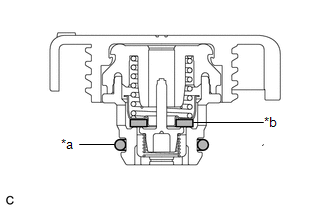
| (b) Check the reserve tank cap operation. (1) Apply coolant to the O-ring and rubber packing before using a radiator cap tester. (2) Install the reserve tank cap to the radiator cap tester. (3) Pump the radiator cap tester several times and check the maximum pressure. Judgment Criterion
NOTICE: When using the radiator cap tester, tilt it upward 30° or more. HINT: If the maximum pressure is less than the minimum standard value, replace the reserve tank cap. |
|
READ NEXT:
 Replacement
REPLACEMENT CAUTION / NOTICE / HINT CAUTION: To avoid the danger of being burned, do not remove the reserve tank cap or drain cock plug while the coolant (for inverter) is still hot. Pressurized, hot
Precaution
PRECAUTION PRECAUTION WHEN REMOVING/INSTALLING INVERTER WITH CONVERTER ASSEMBLY CAUTION:
Be careful not to injure yourself on the edges of the inverter with converter assembly when performing work.
SEE MORE:
Operation Panel Disconnected (B15D9)
DESCRIPTION The multi-display assembly and air conditioning control assembly are connected by AVC-LAN communication lines. This DTC is stored when an AVC-LAN communication error occurs between the multi-display assembly and air conditioning control assembly. DTC No. Detection Item DTC Detecti
Driver Seat Control ECU Communication Stop Mode
DESCRIPTION Detection Item Symptom Trouble Area Driver Seat Control ECU Communication Stop Mode Any of the following conditions are met:
Communication stop for "D-Seat" is indicated on the "Communication Bus Check" screen of the Techstream.
Click here
Communication stop history
