Lexus ES: Mirror Heater does not Operate with Rear Defogger Switch
DESCRIPTION
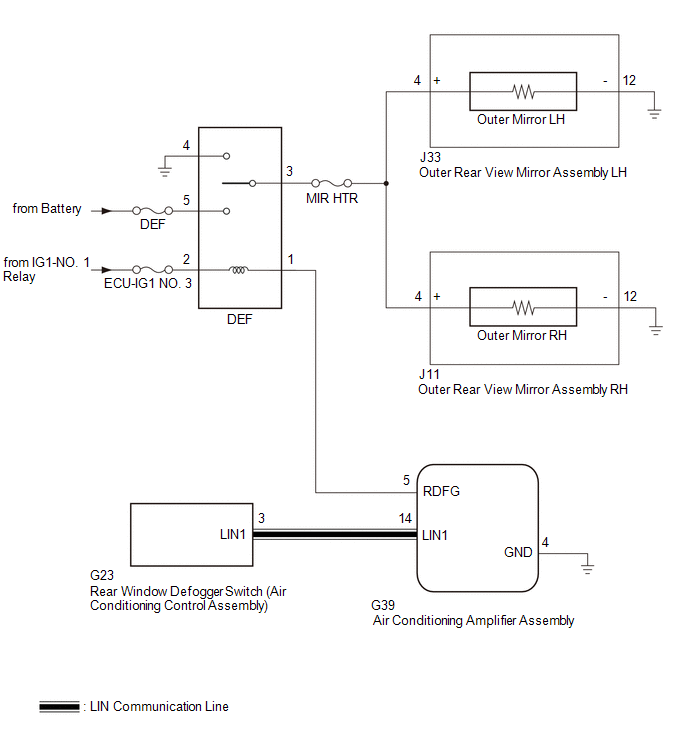
When the mirror heater switch (rear window defogger switch) on the air conditioning control assembly is pressed, the operation signal is sent to the air conditioning amplifier assembly via LIN communication. When the air conditioning amplifier assembly receives the signal, it turns on the DEF relay to operate the mirror heaters.
WIRING DIAGRAM
CAUTION / NOTICE / HINT
NOTICE:
- Inspect the fuses for circuits related to this system before performing the following procedure.
- If the battery voltage becomes low, battery load control will operate in order to ensure sufficient power is supplied to the power steering system. In this case, the window defogger system may not operate.
PROCEDURE
| 1. | PERFORM ACTIVE TEST USING TECHSTREAM |
(a) Connect the Techstream to the DLC3.
(b) Turn the engine switch on (IG).
(c) Turn the Techstream on.
(d) Enter the following menus: Body Electrical / Air Conditioner / Active Test.
(e) Perform the Active Test according to the display on the Techstream.
Body Electrical > Air Conditioner > Active Test| Tester Display | Measurement Item | Control Range | Diagnostic Note |
|---|---|---|---|
| Defogger Relay (Rear) | Mirror Heater operation | OFF or ON | - |
| Tester Display |
|---|
| Defogger Relay (Rear) |
| Result | Proceed to |
|---|---|
| Mirror heater operation on both mirrors is not normal | A |
| Mirror heater operation on RH side mirror is not normal | B |
| Mirror heater operation on LH side mirror is not normal | C |
| B | .gif) | GO TO STEP 4 |
| C | | GO TO STEP 6 |
|
.gif)
| 2. | CHECK WINDOW DEFOGGER SYSTEM |
(a) Check the window defogger system operation.
Click here .gif)
OK:
The window defogger system operates normally.
| NG | | GO TO WINDOW DEFOGGER SYSTEM |
|
| 3. | CHECK HARNESS AND CONNECTOR (DEF RELAY - OUTER REAR VIEW MIRROR ASSEMBLY RH/LH) |
(a) Remove the DEF relay from the No. 1 engine room relay block and No. 1 junction block assembly.
(b) Disconnect the J33 outer rear view mirror assembly LH connector.
(c) Disconnect the J11 outer rear view mirror assembly RH connector.
(d) Measure the resistance according to the value(s) in the table below.
Standard Resistance:
| Tester Connection | Condition | Specified Condition |
|---|---|---|
| DEF relay holder terminal-3 - J33-4 (+) | Always | Below 1 Ω |
| DEF relay holder terminal-3 - J11-4 (+) | Always | Below 1 Ω |
| DEF relay holder terminal-3 , J33-4 (+) or J11-4 (+) - Body ground | Always | 10 kΩ or higher |
| OK | | USE SIMULATION METHOD TO CHECK |
| NG | | REPAIR OR REPLACE HARNESS OR CONNECTOR |
| 4. | CHECK HARNESS AND CONNECTOR (DEF RELAY - OUTER REAR VIEW MIRROR ASSEMBLY RH AND BODY GROUND) |
(a) Remove the DEF relay from the No. 1 engine room relay block and No. 1 junction block assembly.
(b) Disconnect the J33 outer rear view mirror assembly LH connector.
(c) Disconnect the J11 outer rear view mirror assembly RH connector.
(d) Measure the resistance according to the value(s) in the table below.
Standard Resistance:
| Tester Connection | Condition | Specified Condition |
|---|---|---|
| DEF relay holder terminal-3 - J11-4 (+) | Always | Below 1 Ω |
| J11-12 (-) - Body ground | Always | Below 1 Ω |
| DEF relay holder terminal-3 or J11-4 (+) - Body ground | Always | 10 kΩ or higher |
| NG | | REPAIR OR REPLACE HARNESS OR CONNECTOR |
|
| 5. | INSPECT OUTER MIRROR RH |
(a) Remove the outer mirror RH.
Click here
(b) Inspect the outer mirror RH.
Click here
OK:
Outer mirror RH is normal.
| OK | | REPLACE OUTER REAR VIEW MIRROR ASSEMBLY RH |
| NG | | REPLACE OUTER MIRROR RH |
| 6. | CHECK HARNESS AND CONNECTOR (DEF RELAY - OUTER REAR VIEW MIRROR ASSEMBLY LH AND BODY GROUND) |
(a) Remove the DEF relay from the No. 1 engine room relay block and No. 1 junction block assembly.
(b) Disconnect the J33 outer rear view mirror assembly LH connector.
(c) Disconnect the J11 outer rear view mirror assembly RH connector.
(d) Measure the resistance according to the value(s) in the table below.
Standard Resistance:
| Tester Connection | Condition | Specified Condition |
|---|---|---|
| DEF relay holder terminal-3 - J33-4 (+) | Always | Below 1 Ω |
| J33-12 (-) - Body ground | Always | Below 1 Ω |
| DEF relay holder terminal-3 or J33-4 (+) - Body ground | Always | 10 kΩ or higher |
| NG | | REPAIR OR REPLACE HARNESS OR CONNECTOR |
|
| 7. | INSPECT OUTER MIRROR LH |
(a) Remove the outer mirror LH.
Click here
(b) Inspect the outer mirror LH.
Click here
OK:
Outer mirror LH is normal.
| OK | | REPLACE OUTER REAR VIEW MIRROR ASSEMBLY LH |
| NG | | REPLACE OUTER MIRROR LH |
READ NEXT:
 Precaution
PRECAUTION PRECAUTION FOR DISCONNECTING CABLE FROM NEGATIVE AUXILIARY BATTERY TERMINAL NOTICE: When disconnecting the cable from the negative (-) auxiliary battery terminal, initialize the following s
Parts Location
PARTS LOCATION ILLUSTRATION *1 OUTER REAR VIEW MIRROR ASSEMBLY (DRIVER DOOR) *2 OUTER REAR VIEW MIRROR ASSEMBLY (FRONT PASSENGER DOOR) *3 OUTER MIRROR (DRIVER DOOR) *4 OUTER MIRROR
SEE MORE:
System Diagram
SYSTEM DIAGRAM Communication Table Transmitter Receiver Signal Communication Method Rear Window Defogger Switch (Air Conditioning Control Assembly) Air Conditioning Amplifier Assembly Rear Window Defogger Switch Signal LIN
Problem Symptoms Table
PROBLEM SYMPTOMS TABLE HINT:
Inspect the fuses and relays related to this system before inspecting the suspected areas below.
Use the table below to help determine the cause of problem symptoms. If multiple suspected areas are listed, the potential causes of the symptoms are listed in order of
