
Lexus ES: Parts Location
PARTS LOCATION
ILLUSTRATION
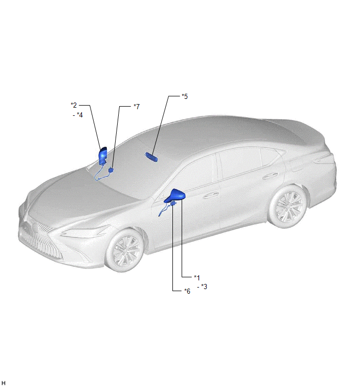
| *1 | OUTER REAR VIEW MIRROR ASSEMBLY (DRIVER DOOR) | *2 | OUTER REAR VIEW MIRROR ASSEMBLY (FRONT PASSENGER DOOR) |
| *3 | OUTER MIRROR (DRIVER DOOR) | *4 | OUTER MIRROR (FRONT PASSENGER DOOR) |
| *5 | INNER REAR VIEW MIRROR ASSEMBLY | *6 | OUTER MIRROR CONTROL ECU ASSEMBLY (DRIVER DOOR) |
| *7 | OUTER MIRROR CONTROL ECU ASSEMBLY (FRONT PASSENGER DOOR) | - | - |
ILLUSTRATION
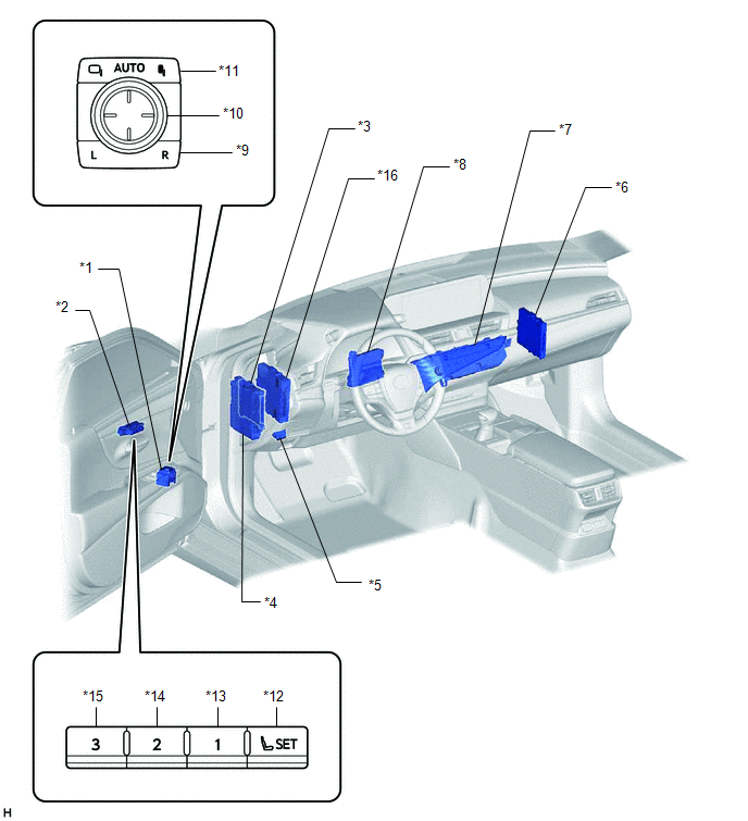
| *1 | OUTER MIRROR SWITCH ASSEMBLY | *2 | SEAT MEMORY SWITCH |
| *3 | MAIN BODY ECU (MULTIPLEX NETWORK BODY ECU) | *4 | INSTRUMENT PANEL JUNCTION BLOCK ASSEMBLY - DOOR F/R FUSE - DOOR F/L FUSE - ECU-IG1 NO. 4 FUSE - ECU-DCC NO. 2 FUSE |
| *5 | DLC3 | *6 | CERTIFICATION ECU (SMART KEY ECU ASSEMBLY) |
| *7 | REAR WINDOW DEFOGGER SWITCH (AIR CONDITIONING CONTROL ASSEMBLY) | *8 | AIR CONDITIONING AMPLIFIER ASSEMBLY |
| *9 | MIRROR SELECT SWITCH | *10 | MIRROR ADJUST SWITCH |
| *11 | RETRACTABLE OUTER MIRROR SWITCH | *12 | SET SWITCH |
| *13 | M1 SWITCH | *14 | M2 SWITCH |
| *15 | M3 SWITCH | *16 | HYBRID VEHICLE CONTROL ECU |
READ NEXT:
 System Diagram
SYSTEM DIAGRAM Communication Table Sender Receiver Signal Line Main Body ECU (Multiplex Network Body ECU) Outer Mirror Control ECU Assembly
IG signal
ACC signal
Outer mirror
System Description
SYSTEM DESCRIPTION POWER MIRROR CONTROL SYSTEM (w/ Memory) DESCRIPTION (a) This system has the following functions: electrical remote control mirror function, memory and reactivation function, power r
How To Proceed With Troubleshooting
CAUTION / NOTICE / HINT HINT:
Use the following procedure to troubleshoot the power mirror control system (w/ Memory).
*: Use the Techstream.
PROCEDURE 1. VEHICLE BROUGHT TO WORKSHOP
SEE MORE:
Portable Player cannot be Connected Manually/Automatically
CAUTION / NOTICE / HINT HINT: Some versions of "Bluetooth" compatible audio players may not function properly, or the functions may be limited using the radio receiver assembly, even if the portable audio player itself can play files. Click here PROCEDURE 1. CHECK CONNECTED DEVICE SETTINGS
Precaution
PRECAUTION PRECAUTIONS FOR INSPECTING POWER SOURCE FOR MAIN BODY ECU (MULTIPLEX NETWORK BODY ECU) NOTICE: When disconnecting the cable from the negative (-) battery terminal, initialize the following systems after the cable is reconnected. System Name See Procedure Lane Control System (for
