Lexus ES: Installation
INSTALLATION
CAUTION / NOTICE / HINT
NOTICE:
- Avoid any impact to the blind spot monitor sensor.
- Do not drop the blind spot monitor sensor. If it is dropped, replace it with a new one.
HINT:
- The blind spot monitor beam axis confirmation is performed to confirm whether the sensor beam axis is correct, and to adjust the beam axis by using a reflector.
- The blind spot monitor sensor installation condition inspection is performed to confirm whether the sensor is perpendicular to the floor surface (+/-2.2°) by using a digital angle gauge, and that the sensor is 46 to 54° from the line parallel to the vehicle center line.
PROCEDURE
1. INSTALL BLIND SPOT MONITOR SENSOR LH
(a) Connect the connector.
(b) Install the blind spot monitor sensor LH with the 3 nuts.
Torque:
10 N·m {102 kgf·cm, 7 ft·lbf}
2. INSTALL BLIND SPOT MONITOR SENSOR RH
(a) Connect the connector.
(b) Install the blind spot monitor sensor RH with the 3 nuts.
Torque:
10 N·m {102 kgf·cm, 7 ft·lbf}
3. INSTALL BLIND SPOT MONITOR COVER LH
(a) Engage the 2 guides and 2 claws to install the blind spot monitor cover LH as shown in the illustration.
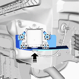
.png) | Install in this Direction |
4. INSTALL BLIND SPOT MONITOR COVER RH
(a) Engage the 2 guides and 2 claws to install the blind spot monitor cover RH as shown in the illustration.
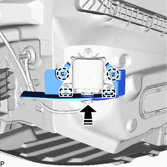
| | Install in this Direction |
5. PERFORM BLIND SPOT MONITOR SENSOR INSTALLATION CONDITION INSPECTION
Click here .gif)
6. INSTALL REAR BUMPER ASSEMBLY
for Single Type: Click here
for Dual Type: Click here
7. PERFORM BLIND SPOT MONITOR BEAM AXIS CONFIRMATION
Click here
8. PERFORM DIAGNOSTIC SYSTEM CHECK
for HV Model: Click here
for Gasoline Model: Click here
READ NEXT:
 Removal
REMOVAL CAUTION / NOTICE / HINT The necessary procedures (adjustment, calibration, initialization, or registration) that must be performed after parts are removed and installed, or replaced during bli
Vehicle Speed Sensor (C1A45)
DESCRIPTION The blind spot monitor sensor receives vehicle speed signals from the skid control ECU via CAN communication. Blind Spot Monitor Master DTC No. Detection Item DTC Detection Conditio
SEE MORE:
Installation
INSTALLATION PROCEDURE 1. INSTALL BATTERY COOLING BLOWER BRACKET (a) Install the battery cooling blower bracket to the battery cooling blower assembly with the 3 bolts. Torque: 7.5 N·m {76 kgf·cm, 66 in·lbf} (b) Engage the clamp. 2. INSTALL BATTERY COOLING BLOWER ASSEMBLY (a) Install the battery
DCM Data Signal Circuit between Navigation ECU and DCM
DESCRIPTION This circuit is used to send and receive signals between the DCM (Telematics Transceiver), radio receiver assembly and navigation ECU. WIRING DIAGRAM PROCEDURE 1. CHECK HARNESS AND CONNECTOR (RADIO RECEIVER ASSEMBLY - DCM (TELEMATICS TRANSCEIVER)) (a) Disconnect the G128 DCM (T
