Lexus ES: Removal
REMOVAL
CAUTION / NOTICE / HINT
The necessary procedures (adjustment, calibration, initialization, or registration) that must be performed after parts are removed and installed, or replaced during blind spot monitor sensor removal/installation are shown below.
Necessary Procedure After Parts Removed/Installed/Replaced (for HV Model)| Replaced Part or Performed Procedure | Necessary Procedure | Effect/Inoperative Function When Necessary Procedures are not Performed | Link |
|---|---|---|---|
|
*1: w/ Hands Free Power Trunk Lid
*2: w/ Parking Support Brake System *3: When performing learning using the Techstream. Click here | |||
| Disconnect cable from negative auxiliary battery terminal*1 | Perform steering sensor zero point calibration | Lane Control System | |
| Pre-collision System | |||
| Parking Support Brake System*3 | |||
| Lighting System | |||
| Memorize steering angle neutral point | Parking Assist Monitor System | | |
| Panoramic View Monitor System | | ||
| Initialize power trunk lid system | Power Trunk Lid System | | |
| Blind spot monitor sensor | Blind spot monitor beam axis adjustment |
| |
| Rear bumper assembly*2 |
|
| |
NOTICE:
- After the power switch is turned off, the radio receiver assembly records various types of memory and settings. As a result, after turning the power switch off, make sure to wait at least 85 seconds before disconnecting the cable from the negative (-) auxiliary battery terminal. (for Audio and Visual System)
- After the power switch is turned off, the radio receiver assembly records various types of memory and settings. As a result, after turning the power switch off, make sure to wait at least 85 seconds before disconnecting the cable from the negative (-) auxiliary battery terminal. (for Navigation System)
| Replaced Part or Performed Procedure | Necessary Procedure | Effect/Inoperative Function When Necessary Procedures are not Performed | Link |
|---|---|---|---|
|
*1: w/ Hands Free Power Trunk Lid
*2: w/ Parking Support Brake System *3: When performing learning using the Techstream. Click here | |||
| Disconnect cable from negative battery terminal*1 | Perform steering sensor zero point calibration | Lane Control System | |
| Pre-collision System | |||
| Parking Support Brake System*3 | |||
| Lighting System | |||
| Memorize steering angle neutral point | Parking Assist Monitor System | | |
| Panoramic View Monitor System | | ||
| Initialize power trunk lid system | Power Trunk Lid System | | |
| Blind spot monitor sensor | Blind spot monitor beam axis adjustment |
| |
| Rear bumper assembly*2 |
|
| |
NOTICE:
- After the engine switch is turned off, the radio receiver assembly records various types of memory and settings. As a result, after turning the engine switch off, make sure to wait at least 85 seconds before disconnecting the cable from the negative (-) battery terminal. (for Audio and Visual System)
- After the engine switch is turned off, the radio receiver assembly records various types of memory and settings. As a result, after turning the engine switch off, make sure to wait at least 85 seconds before disconnecting the cable from the negative (-) battery terminal. (for Navigation System)
PROCEDURE
1. REMOVE REAR BUMPER ASSEMBLY
for Single Type: Click here .gif)
for Dual Type: Click here
2. REMOVE BLIND SPOT MONITOR COVER LH
(a) Disengage the 2 claws and 2 guides to remove the blind spot monitor cover LH as shown in the illustration.
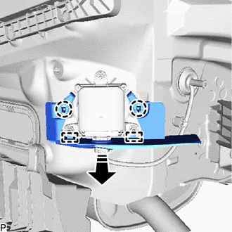
.png) | Remove in this Direction |
3. REMOVE BLIND SPOT MONITOR COVER RH
(a) Disengage the 2 claws and 2 guides to remove the blind spot monitor cover RH as shown in the illustration.
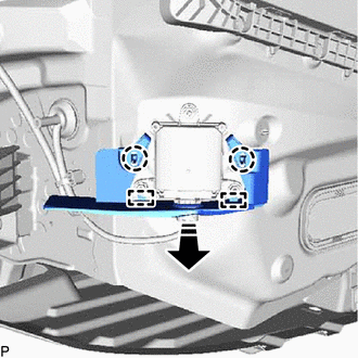
| | Remove in this Direction |
4. REMOVE BLIND SPOT MONITOR SENSOR LH
| (a) Disconnect the connector. |
|
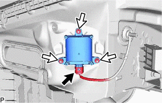
(b) Remove the 3 nuts and blind spot monitor sensor LH.
NOTICE:
Replace the blind spot monitor sensor LH if it has been dropped or subjected to a severe impact.
5. REMOVE BLIND SPOT MONITOR SENSOR RH
| (a) Disconnect the connector. |
|
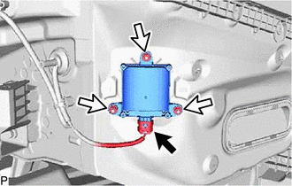
(b) Remove the 3 nuts and blind spot monitor sensor RH.
NOTICE:
Replace the blind spot monitor sensor RH if it has been dropped or subjected to a severe impact.
READ NEXT:
 Vehicle Speed Sensor (C1A45)
DESCRIPTION The blind spot monitor sensor receives vehicle speed signals from the skid control ECU via CAN communication. Blind Spot Monitor Master DTC No. Detection Item DTC Detection Conditio
Yaw Rate Sensor (C1A46)
DESCRIPTION The blind spot monitor sensor receives yaw rate signals from the airbag sensor assembly (yaw rate and acceleration sensor) via CAN communication. Blind Spot Monitor Master DTC No. Det
SEE MORE:
Data List / Active Test
DATA LIST / ACTIVE TEST DATA LIST NOTICE: In the table below, the values listed under "Normal Condition" are reference values. Do not depend solely on these reference values when deciding whether a part is faulty or not. HINT: Using the Techstream to read the Data List allows the values or states of
Hybrid/EV Battery Current Sensor for Driving Control Circuit Short to Ground (P1C9F11,P1C9F15)
DESCRIPTION Refer to the description for DTC P0ABF11. Click here DTC No. Detection Item DTC Detection Condition Trouble Area MIL Warning Indicate P1C9F11 Hybrid/EV Battery Current Sensor for Driving Control Circuit Short to Ground Value of "Hybrid Battery Current for Driving C
