Lexus ES: Disassembly
DISASSEMBLY
PROCEDURE
1. REMOVE BRAKE MASTER CYLINDER STRAIGHT PIN
(a) Secure the brake master cylinder sub-assembly in a vise.
NOTICE:
Place aluminum plates on the vise to prevent damage to the brake master cylinder sub-assembly.
| (b) Using a 5 mm pin punch and a hammer, tap out the brake master cylinder straight pin from the brake master cylinder sub-assembly. NOTICE: Do not drop the brake master cylinder reservoir assembly. |
|

2. REMOVE BRAKE MASTER CYLINDER RESERVOIR ASSEMBLY
(a) Remove the brake master cylinder reservoir assembly from the brake master cylinder body.
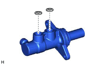
3. REMOVE MASTER CYLINDER RESERVOIR GROMMET
| (a) Remove the 2 master cylinder reservoir grommets from the brake master cylinder body. |
|
(b) Remove the brake master cylinder body from the vise.
4. REMOVE BRAKE MASTER CYLINDER RESERVOIR FILLER CAP ASSEMBLY
5. REMOVE BRAKE MASTER CYLINDER RESERVOIR STRAINER
READ NEXT:
 Inspection
INSPECTION PROCEDURE 1. INSPECT AND ADJUST BRAKE BOOSTER PUSH ROD NOTICE: Make the adjustment with no vacuum in the brake booster assembly. (Depress the brake pedal several times with the engine stopp
Installation
INSTALLATION PROCEDURE 1. INSPECT AND ADJUST BRAKE BOOSTER PUSH ROD Click here 2. INSTALL BRAKE MASTER CYLINDER O-RING (a) Install a new brake master cylinder O-ring to the brake master cylinder sub
Reassembly
REASSEMBLY PROCEDURE 1. INSTALL BRAKE MASTER CYLINDER RESERVOIR STRAINER 2. INSTALL BRAKE MASTER CYLINDER RESERVOIR FILLER CAP ASSEMBLY 3. INSTALL MASTER CYLINDER RESERVOIR GROMMET (a) Apply a light l
SEE MORE:
Components
COMPONENTS ILLUSTRATION *A for LH Side - - *1 COWL SIDE TRIM BOARD LH *2 FRONT DOOR OPENING TRIM COVER LH *3 FRONT DOOR SCUFF PLATE LH *4 INSTRUMENT SIDE PANEL LH *5 LOWER INSTRUMENT PANEL FINISH PANEL SUB-ASSEMBLY *6 NO. 1 INSTRUMENT PANEL UNDER COVER SUB-ASS
Components
COMPONENTS ILLUSTRATION *A w/ Power Trunk Lid System - - *1 LUGGAGE COMPARTMENT DOOR COVER *2 LUGGAGE LOCK CONTROL CABLE PLATE *3 SWITCH BEZEL - - ILLUSTRATION *1 REAR LIGHT ASSEMBLY *2 REAR LIGHT GASKET *3 REAR LIGHT PROTECTOR - - N*m (kgf
