Lexus ES: Installation
INSTALLATION
PROCEDURE
1. INSTALL ACCELERATION SENSOR ASSEMBLY LH (for LH Side)
| (a) Install the acceleration sensor assembly LH with the 2 nuts. Torque: 13 N·m {133 kgf·cm, 10 ft·lbf} NOTICE:
|
|
.png)
(b) Engage the clamp.
(c) Connect the connector to the acceleration sensor assembly LH.
2. INSTALL ACCELERATION SENSOR ASSEMBLY RH (for RH Side)
| (a) Insert the acceleration sensor assembly RH to the connector holder. |
|
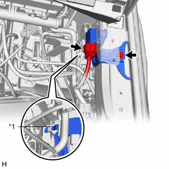
(b) Install the acceleration sensor assembly RH with the bolt.
Torque:
7.5 N·m {76 kgf·cm, 66 in·lbf}
NOTICE:
- Avoid any impact to the acceleration sensor assembly RH.
- Do not drop the acceleration sensor assembly RH. If it is dropped, replace it with a new one.
(c) Connect the connector to the acceleration sensor assembly RH.
3. INSTALL LOWER INSTRUMENT PANEL FINISH PANEL SUB-ASSEMBLY (for LH Side)
Click here .gif)
4. INSTALL INSTRUMENT SIDE PANEL LH (for LH Side)
Click here
5. INSTALL FRONT DOOR OPENING TRIM COVER LH (for LH Side)
Click here
6. INSTALL NO. 1 INSTRUMENT PANEL UNDER COVER SUB-ASSEMBLY (for LH Side)
Click here
7. INSTALL COWL SIDE TRIM BOARD LH (for LH Side)
Click here
8. INSTALL FRONT DOOR SCUFF PLATE LH (for LH Side)
Click here
9. INSTALL LOWER INSTRUMENT FINISH SUB PANEL (for RH Side)
Click here
10. INSTALL INSTRUMENT SIDE PANEL RH (for RH Side)
Click here
11. INSTALL FRONT DOOR OPENING TRIM COVER RH (for RH Side)
HINT:
Use the same procedure as for the LH side.
Click here
12. INSTALL COWL SIDE TRIM BOARD RH (for RH Side)
HINT:
Use the same procedure as for the LH side.
Click here
13. INSTALL FRONT DOOR SCUFF PLATE RH (for RH Side)
HINT:
Use the same procedure as for the LH side.
Click here
READ NEXT:
 Relay
Relay
On-vehicle InspectionON-VEHICLE INSPECTION PROCEDURE 1. INSPECT AVS RELAY (a) Measure the resistance according to the value(s) in the table below. Standard Resistance: Tester Connection Cond
Components
COMPONENTS ILLUSTRATION *A for Type A *B for Type B *1 LUGGAGE COMPARTMENT FLOOR MAT *2 LUGGAGE COMPARTMENT TRIM COVER RH *3 LUGGAGE COMPARTMENT TRIM INNER COVER RH *4 RE
SEE MORE:
Headlight Beam Level Control Motor LH Lost Communication (B2424,B2425)
DESCRIPTION Each headlight ECU sub-assembly and headlight leveling motor communicate via LIN communication. The headlight leveling motor operates according to power supplied and automatic headlight beam level control signals from its respective headlight ECU sub-assembly and sends its operating stat
Precaution
PRECAUTION CHARGING SYSTEM PRECAUTION CAUTION:
Orange wire harnesses and connectors indicate high-voltage circuits. To prevent electric shock, always follow the procedure described in the repair manual. Click here
To prevent electric shock, wear insulated gloves when working on wire harnesse
