Lexus ES: Hydraulic Test
HYDRAULIC TEST
PERFORM HYDRAULIC TEST
CAUTION:
-
Do not perform a stall test if there are any people or objects near the vehicle.
.png)
- The vehicle could begin moving suddenly, resulting in a serious accident.
-
Do not perform a stall test if any wheel chocks are out of position.
.png)
- The vehicle could begin moving suddenly, resulting in a serious accident.
-
Do not perform the stall test on a slippery or low-friction surface that could allow the tires to spin.
.png)
- The vehicle could begin moving suddenly, resulting in a serious accident.
(a) Measure the line pressure.
NOTICE:
- Perform this test with the ATF (Automatic Transaxle Fluid) at the normal operating temperature: 50 to 80°C (122 to 176°F)
- Be careful to prevent the SST hose from contacting the exhaust pipe.
- This check must be conducted after checking and confirming that the engine is normal.
- Perform this test with the air conditioning off.
- Do not perform the stall test for longer than 5 seconds.
- When performing the stall speed test repeatedly, wait for 15 seconds or more between tests.
- The installation position of SST is different for the D position and R position line pressure tests.
- Perform this test with the AUTO function (shift-linked function) of the electronic parking brake system off.
-
Check that there is no obstruction within 5 m (16.4 ft.) of the driving direction (forward of the vehicle when the shift lever in D, and behind the vehicle when the shift lever in R).
When torque is restricted by a safety function of the intelligent clearance sonar system, etc., the stall characteristics may not be normal.
(1) Warm up the ATF.
(2) Lift the vehicle.
(3) Remove the engine under cover.
(4) Remove the test plug A on the front side of the transaxle case and install SST.
SST: 09993-19015
09993-00010
09993-00040
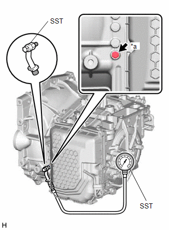
| *a | Test Plug A |
(5) Lower the vehicle.
(6) Fully apply the parking brake and chock all 4 wheels.
HINT:
When the parking brake indicator (red) is illuminated after the electric parking brake switch (electric parking brake switch assembly) has been pulled to the lock side, the maximum amount of braking force is applied if the electric parking brake switch (electric parking brake switch assembly) is pulled to the lock side one more time.
(7) Start the engine and check the idle speed.
(8) Keep your left foot firmly on the brake pedal and move the shift lever to D.
(9) Measure the line pressure while the engine is idling.
Specified Line Pressure:
| Condition | D Position |
|---|---|
| Engine idling | 500 to 700 kPa (5.1 to 7.1 kgf/cm2, 73 to 102 psi) |
(10) Depress the accelerator pedal as much as possible with your right foot. Quickly read the highest line pressure reading when the engine speed reaches stall speed.
Specified Line Pressure:
| Condition | D Position |
|---|---|
| Stall test | 1300 to 1600 kPa (13.3 to 16.3 kgf/cm2, 189 to 232 psi) |
(11) Turn the engine switch off.
(12) Remove SST and install the test plug A.
(13) Remove the test plug B on the left side of the transaxle case and install SST.
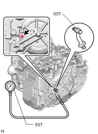
| *a | Test Plug B |
SST: 09993-19015
09993-00010
09993-00040
(14) Start the engine and check the idle speed.
(15) Keep your left foot firmly on the brake pedal and move the shift lever to R.
(16) Measure the line pressure while the engine is idling.
Specified Line Pressure:
| Condition | R Position |
|---|---|
| Engine idling | 575 to 825 kPa (5.9 to 8.4 kgf/cm2, 83 to 120 psi) |
(17) Depress the accelerator pedal as much as possible with your right foot. Quickly read the highest line pressure reading when the engine speed reaches stall speed.
Specified Line Pressure:
| Condition | R Position |
|---|---|
| Stall test | 1700 to 2100 kPa (17.3 to 21.4 kgf/cm2, 247 to 305 psi) |
(18) Turn the engine switch off.
(19) Remove SST and install the test plug B.
(20) Clear the DTCs.
Click here .gif)
| Problem | Possible Cause |
|---|---|
| Measured values at all positions are higher than specified |
|
| Measured values at all positions are lower than specified |
|
| Pressure is low when shift lever is in D only |
|
| Pressure is low when shift lever is in R only |
|
READ NEXT:
 Initialization
INITIALIZATION RESET TRANSAXLE COMPENSATION CODE NOTICE:
If the following parts have been replaced, initialize the ECM, perform Reset Memory and Perform Road Test to Allow ECM to Learn.
ECM (Whe
Manual Shifting Test
MANUAL SHIFTING TEST MANUAL SHIFTING TEST HINT:
Using this test, it can be determined whether a problem is in an electrical circuit or if it is a mechanical problem in the transaxle.
If any abnor
Mechanical System Tests
MECHANICAL SYSTEM TESTS STALL SPEED TEST CAUTION:
Do not perform a stall test if there are any people or objects near the vehicle.
The vehicle could begin moving suddenly, resulting in a serious
SEE MORE:
Dtc Check / Clear
DTC CHECK / CLEAR CHECK FOR DTCS (a) Connect the Techstream to the DLC3. (b) Turn the power switch on (IG). (c) Turn the Techstream on. (d) Enter the following menus: Powertrain / HV battery / Trouble Codes. Powertrain > HV Battery > Trouble Codes (e) Check the DTCs and freeze frame data, and
Installation
INSTALLATION PROCEDURE 1. INSTALL NO. 2 CLEARANCE WARNING BUZZER (a) Connect the connector. (b) Engage the clamp to install the No. 2 clearance warning buzzer. 2. INSTALL PACKAGE TRAY TRIM PANEL ASSEMBLY (w/o Rear Sunshade) Click here 3. INSTALL PACKAGE TRAY TRIM PANEL ASSEMBLY (w/ Rear Sunshade)
