Lexus ES: Inspection
INSPECTION
PROCEDURE
1. INSPECT POWER WINDOW REGULATOR MOTOR ASSEMBLY (FOR REAR LH DOOR)
| (a) Connect a positive (+) lead from the auxiliary battery to connector terminal 2. NOTICE: Do not connect a positive (+) lead from the auxiliary battery to any terminal other than terminal 2 to avoid damaging the pulse sensor inside the motor. |
|
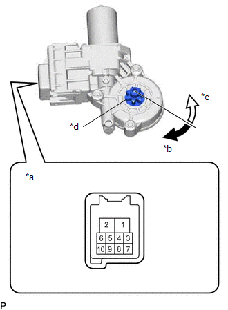
(b) Connect a negative (-) lead from the auxiliary battery to connector terminals 1 and 7 or 10.
(c) Check that the motor gear rotates smoothly as follows:
OK:
| Measurement Condition | Specified Condition |
|---|---|
| Motor gear rotates clockwise |
| Motor gear rotates counterclockwise |
- If the result is not as specified, replace the power window regulator motor assembly (for rear LH door).
CAUTION:
Initialize the power window control system after installing the rear door window regulator assembly.
2. INSPECT POWER WINDOW REGULATOR MOTOR ASSEMBLY (FOR REAR RH DOOR)
| (a) Connect a positive (+) lead from the auxiliary battery to connector terminal 2. NOTICE: Do not connect a positive (+) lead from the auxiliary battery to any terminal other than terminal 2 to avoid damaging the pulse sensor inside the motor. |
|
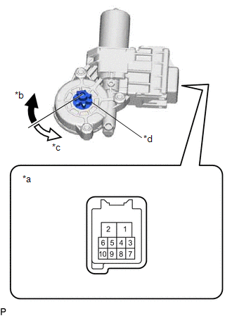
(b) Connect a negative (-) lead from the auxiliary battery to connector terminals 1 and 7 or 10.
(c) Check that the motor gear rotates smoothly as follows:
OK:
| Measurement Condition | Specified Condition |
|---|---|
| Motor gear rotates counterclockwise |
| Motor gear rotates clockwise |
- If the result is not as specified, replace the power window regulator motor assembly (for rear RH door).
CAUTION:
Initialize the power window control system after installing the rear door window regulator assembly.
READ NEXT:
 Installation
INSTALLATION CAUTION / NOTICE / HINT HINT:
Use the same procedure for the RH side and LH side.
The following procedure is for the LH side.
PROCEDURE 1. PRECAUTION NOTICE: After turning the eng
Rear Power Window Switch
ComponentsCOMPONENTS ILLUSTRATION *1 REAR POWER WINDOW REGULATOR SWITCH ASSEMBLY *2 REAR POWER WINDOW REGULATOR SWITCH ASSEMBLY WITH REAR DOOR UPPER ARMREST BASE PANEL RemovalREMOVAL CA
Relay
On-vehicle InspectionON-VEHICLE INSPECTION PROCEDURE 1. INSPECT DEF RELAY (a) Measure the resistance according to the value(s) in the table below. Standard Resistance: Tester Connection Cond
SEE MORE:
Control Module Communication Bus Off (U0073,U0100,U0126,U0129,U0140,U0163,U0233,U023B,U0265,U1110)
DESCRIPTION These DTCs are stored if there is a malfunction in the CAN communication system connected to the parking assist ECU. HINT: If CAN communication system DTCs are stored, they may also be stored in other systems. DTC No. Detection Item DTC Detection Condition Trouble Area U0073
Back Camera Disconnected (C1622)
DESCRIPTION This DTC is stored if the radio receiver assembly judges that the signals or signal lines between the rear television camera assembly and the multi-display assembly are not normal as a result of its self check. DTC No. Detection Item DTC Detection Condition Trouble Area C162
