Lexus ES: Relay
On-vehicle Inspection
ON-VEHICLE INSPECTION
PROCEDURE
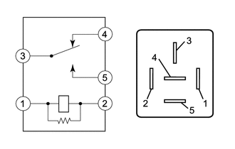
1. INSPECT DEF RELAY
| (a) Measure the resistance according to the value(s) in the table below. Standard Resistance:
If the result is not as specified, replace the DEF relay. |
|
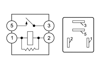
2. INSPECT DEICER RELAY
| (a) Measure the resistance according to the value(s) in the table below. Standard Resistance:
If the result is not as specified, replace the deicer relay. |
|
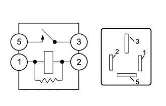
3. INSPECT HWD RELAY
| (a) Measure the resistance according to the value(s) in the table below. Standard Resistance:
If the result is not as specified, replace the HWD relay. |
|
READ NEXT:
 Precaution
PRECAUTION PRECAUTION FOR DISCONNECTING CABLE FROM NEGATIVE BATTERY TERMINAL NOTICE: When disconnecting the cable from the negative (-) battery terminal, initialize the following systems after the cab
Parts Location
PARTS LOCATION ILLUSTRATION *1 DEF RELAY *2 REAR WINDOW DEFOGGER WIRE *3 NO. 1 ENGINE ROOM RELAY BLOCK AND NO. 1 JUNCTION BLOCK ASSEMBLY - DEF FUSE *4 BACK WINDOW GLASS ILLUSTRA
SEE MORE:
Power Trunk Lid does not Operate Using Cabin Switch
DESCRIPTION The trunk and fuel switch assembly (luggage compartment door opening switch) signal is sent to the luggage closer motor assembly. If the power trunk lid does not operate using the trunk and fuel (luggage compartment door opening switch), a trunk and fuel (luggage compartment door opening
Parts Location
PARTS LOCATION ILLUSTRATION *A for Manual Tilt and Manual Telescopic Steering Column *B for Power Tilt and Power Telescopic Steering Column *C w/ Power Trunk Lid System - - *1 MULTIPLEX NETWORK MASTER SWITCH ASSEMBLY *2 INSTRUMENT PANEL JUNCTION BLOCK ASSEMBLY - ECU-B N
