Lexus ES: Installation
INSTALLATION
PROCEDURE
1. INSTALL NAVIGATION ECU
2. INSTALL NO. 1 RADIO RECEIVER BRACKET
(a) Install the No. 1 radio receiver bracket with the 2 screws.
3. INSTALL NAVIGATION ECU WITH BRACKET
(a) Engage the 4 claws to temporarily install the navigation ECU with bracket as shown in the illustration.
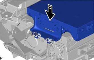
.png) | Install in this Direction |
| (b) Install the 2 screws. |
|
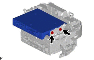
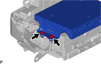
| (c) Install the navigation ECU with bracket with the 2 screws. |
|
4. INSTALL NO. 1 NAVIGATION WIRE
(a) Connect the 2 connectors to install the No. 1 navigation wire.
5. INSTALL RADIO RECEIVER ASSEMBLY WITH SWITCH
Click here .gif)
6. INSTALL LOWER INSTRUMENT PANEL SUB-ASSEMBLY
Click here
7. INSTALL LOWER INSTRUMENT PANEL LH
Click here
8. INSTALL NO. 2 INSTRUMENT PANEL UNDER COVER SUB-ASSEMBLY
Click here
9. INSTALL INSTRUMENT SIDE PANEL RH
Click here
10. INSTALL FRONT DOOR OPENING TRIM COVER RH
HINT:
Use the same procedure as for the LH side.
Click here
11. INSTALL COWL SIDE TRIM BOARD RH
HINT:
Use the same procedure as for the LH side.
Click here
12. INSTALL FRONT DOOR SCUFF PLATE RH
HINT:
Use the same procedure as for the LH side.
Click here
13. INSTALL LOWER INSTRUMENT PANEL
Click here
14. INSTALL UPPER CONSOLE PANEL SUB-ASSEMBLY
Click here
15. INSTALL REAR UPPER CONSOLE PANEL SUB-ASSEMBLY
Click here
16. INSTALL SHIFT LEVER KNOB SUB-ASSEMBLY
for UA80E: Click here
for P710: Click here
17. INSTALL CENTER INSTRUMENT CLUSTER FINISH PANEL SUB-ASSEMBLY
Click here
18. INSTALL INSTRUMENT PANEL FINISH PANEL END RH
Click here
19. INSTALL INSTRUMENT PANEL FINISH PANEL END LH
Click here
READ NEXT:
 Installation
INSTALLATION PROCEDURE 1. INSTALL NAVIGATION ECU 2. INSTALL NO. 1 RADIO RECEIVER BRACKET (a) Install the No. 1 radio receiver bracket with the 2 screws. 3. INSTALL NAVIGATION ECU WITH BRACKET (a) Enga
Removal
REMOVAL PROCEDURE 1. PRECAUTION (for HV Model) NOTICE:
When replacing the radio receiver assembly or navigation ECU, always replace it with a new one. If a radio receiver assembly or navigation ECU
Removal
REMOVAL PROCEDURE 1. PRECAUTION (for HV Model) NOTICE:
When replacing the radio receiver assembly or navigation ECU, always replace it with a new one. If a radio receiver assembly or navigation ECU
SEE MORE:
Parking Brake System
PrecautionPRECAUTION NOTICE:
If the battery is connected, the parking brake will operate when the electric parking brake switch assembly is pulled to the lock side even if the engine switch (for Gasoline Model) or power switch (for HV Model) is off. Do not operate the electric parking brake swit
PIG Power Supply Voltage (C1552,C1554)
DESCRIPTION When a malfunction is detected in the PIG power source and power supply relay system, the fail-safe function suspends power assist. DTC No. Detection Item DTC Detection Condition Trouble Area Warning Indicate Return-to-normal Condition Note C1552 PIG Power Supply Vol
