Lexus ES: Inspection
INSPECTION
PROCEDURE
1. INSPECT REAR HEIGHT CONTROL SENSOR SUB-ASSEMBLY LH (for 2WD)
(a) Preparation for check
(1) Confirm the standard, high and low positions of the link that will be used in the following inspection.
- The standard position is 58° from the maximum link angle (high) and 51° from the maximum link angle (low).
- The high position (+45°) is 13° from the maximum link angle (high).
- The low position (-45°) is 6° from the maximum link angle (low).
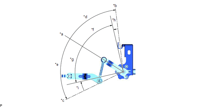
| *a | Standard Position | *b | Maximum Link Angle (Low) |
| *c | Maximum Link Angle (High) | *d | 51° |
| *e | 58° | *f | -45° |
| *g | +45° | *h | 6° |
| *i | 13° | - | - |
(2) Connect 3 dry cell batteries (1.5 V) in series.
NOTICE:
Do not use rechargeable batteries as they may not output a voltage of 1.5 V.
(3) Connect a positive (+) lead from the batteries to terminal 3 (SHB) and a negative (-) lead to terminal 1 (SHG).
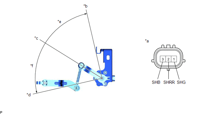
| *a | Component without harness connected (Rear Height Control Sensor Sub-assembly LH) | *b | Low |
| *c | Standard Position | *d | High |
| *e | -45° | *f | +45° |
(4) Measure the voltage between terminals 2 (SHRR) and 1 (SHG) while slowly moving the link up and down.
Standard Voltage:
| Tester Connection | Condition | Specified Condition |
|---|---|---|
| 2 (SHRR) - 1 (SHG) | +45° (High) | 4.5 V |
| 2 (SHRR) - 1 (SHG) | 0° (Standard position) | 2.5 V |
| 2 (SHRR) - 1 (SHG) | -45° (Low) | 0.5 V |
If the result is not as specified, replace the rear height control sensor sub-assembly LH.
2. INSPECT REAR HEIGHT CONTROL SENSOR SUB-ASSEMBLY LH (for AWD)
(a) Check the rear height control sensor sub-assembly LH.
(1) Connect 3 dry batteries of 1.5 V in series.
(2) Connect the positive (+) end of the batteries to terminal 3 (SHB) of the rear height control sensor sub-assembly LH and the negative (-) end of the batteries to terminal 1 (SHG). While slowly moving the sensor link up and down, measure the voltage between terminal 2 (SHRR) and terminal 1 (SHG).
NOTICE:
- Do not use rechargeable batteries as they may not output a voltage of 1.5 V.
- Do not apply a voltage of more than 6 V.
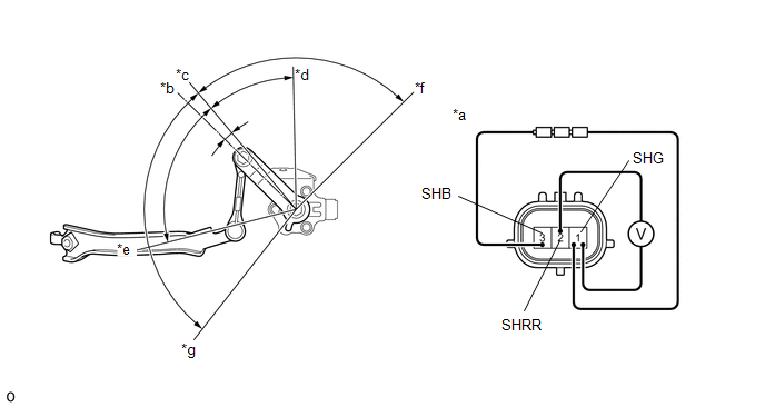
| *a | Component without harness connected (Rear Height Control Sensor Sub-assembly LH) | *b | Standard position (6.5° from horizontal position) |
| *c | Horizontal Position | *d | Height low (Full bound) (18.5° from standard position) |
| *e | Height high (Full rebound) (45.5° from standard position) | *f | Bound side link stop position (85° from standard position) |
| *g | Rebound side link stop position (102° from standard position) | - | - |
(3) Measure the voltage according to the value(s) in the table below.
Standard Voltage:
| Tester Connection | Condition | Specified Condition | |
|---|---|---|---|
| If the result is not as specified, replace the rear height control sensor sub-assembly LH. | |||
| 1 (SHG) - 2 (SHRR) | Link moves upward from standard position to bound side (Height low) | From 18.5° to bound side link stop position | 0.5 V |
| 18.5° (Full Bound) | 1.69 V | ||
| Horizontal Position | - | 2.5 V | |
| Link moves downward from standard position to rebound side (Height high) | Standard position | 2.79 V | |
| 45.5° (Full Rebound) | 4.5 V | ||
| From 45.5° to rebound side link stop position | 4.5 V | ||
READ NEXT:
 Installation
INSTALLATION PROCEDURE 1. INSTALL REAR HEIGHT CONTROL SENSOR SUB-ASSEMBLY LH NOTICE: If the rear height control sensor sub-assembly LH has been struck or dropped, replace it with a new one. (a) for 2W
High Mounted Stop Light Assembly
ComponentsCOMPONENTS ILLUSTRATION *1 CENTER STOP LIGHT SET - - RemovalREMOVAL PROCEDURE 1. REMOVE CENTER STOP LIGHT SET (a) Disengage the 4 guides as shown in the illustration. D
SEE MORE:
Problem Symptoms Table
PROBLEM SYMPTOMS TABLE NOTICE: If the battery voltage is low, the mirror heater function may not operate. HINT:
Use the table below to help determine the cause of problem symptoms. If multiple suspected areas are listed, the potential causes of the symptoms are listed in order of probability in t
Mirror Heater does not Operate with Rear Defogger Switch
DESCRIPTION When the mirror heater switch (rear window defogger switch) is operated, the mirror heater signal is sent to the air conditioning amplifier assembly and then to each outer mirror control ECU assembly via CAN communication. Based on this signal, the outer mirror control ECU assemblies ope
