Lexus ES: High Mounted Stop Light Assembly
Components
COMPONENTS
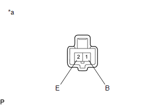
ILLUSTRATION
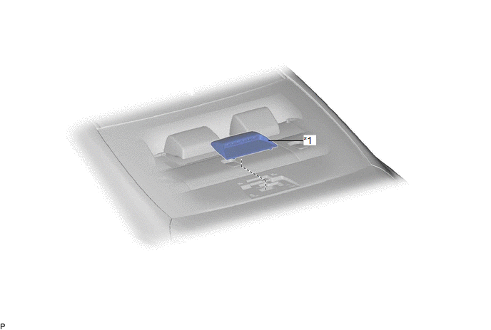
| *1 | CENTER STOP LIGHT SET | - | - |
Removal
REMOVAL
PROCEDURE
1. REMOVE CENTER STOP LIGHT SET
(a) Disengage the 4 guides as shown in the illustration.
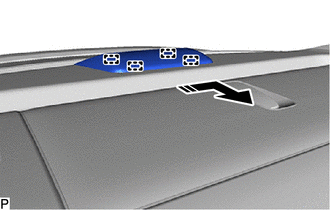
.png) | Disengage in this Direction |
(b) Turn the center stop light set as shown in the illustration.
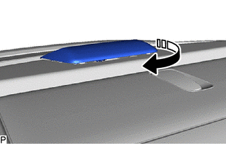
| | Turn in this Direction |
| (c) Disconnect the connector to remove the center stop light set. |
|
Inspection
INSPECTION
PROCEDURE
1. INSPECT CENTER STOP LIGHT SET
| (a) Apply auxiliary battery voltage to the center stop light set and check that the light illuminates. OK:
If the result is not as specified, replace the center stop light set. |
|
Installation
INSTALLATION
PROCEDURE
1. INSTALL CENTER STOP LIGHT SET
(a) Connect the connector.
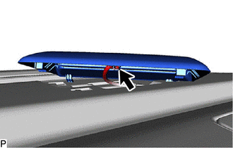
(b) Turn the center stop light set as shown in the illustration.
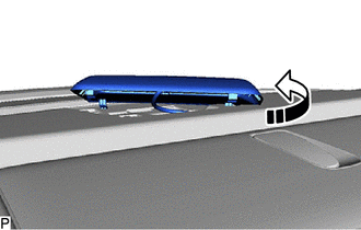
.png) | Turn in this Direction |
(c) Engage the 4 guides as shown in the illustration to install the center stop light set.
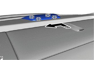
| | Install in this Direction |
READ NEXT:
 Components
COMPONENTS ILLUSTRATION *A for Driver Side *B for Front Passenger Side *1 COURTESY LIGHT ASSEMBLY *2 FRONT DOOR ILLUMINATION LIGHT (FRONT DOOR OUTSIDE HANDLE ASSEMBLY) *3 FRO
Removal
REMOVAL CAUTION / NOTICE / HINT The necessary procedures (adjustment, calibration, initialization or registration) that must be performed after parts are removed and installed, or replaced during fron
SEE MORE:
Removal
REMOVAL CAUTION / NOTICE / HINT The necessary procedures (adjustment, calibration, initialization, or registration) that must be performed after parts are removed and installed, or replaced during black out tape removal/installation are shown below. Necessary Procedure After Parts Removed/Installed/
Diagnostic Trouble Code Chart
DIAGNOSTIC TROUBLE CODE CHART Power Steering System DTC No. Detection Item DTC Detection Condition Warning Indicate Return-to-normal Condition Note Link C1511 Torque Sensor1 Torque sensor malfunction EPS warning light: Comes on Power switch is turned on (IG) again -
