Lexus ES: Microphone Circuit Open (B157213)
DESCRIPTION
This DTC is stored when the DCM (telematics transceiver) detects a malfunction in the telephone microphone assembly circuit.
| DTC No. | Detection Item | DTC Detection Condition | Trouble Area |
|---|---|---|---|
| B157213 | Microphone Circuit Open | Current at terminal MCVD is lower than the malfunction threshold for 10 seconds or more while the engine switch is on (IG) |
|
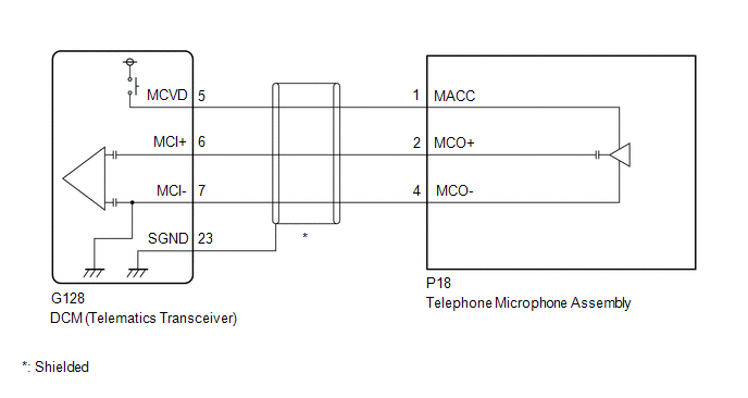
WIRING DIAGRAM
CAUTION / NOTICE / HINT
NOTICE:
Depending on the parts that are replaced during vehicle inspection or maintenance, performing initialization, registration or calibration may be needed. Refer to Precaution for Safety Connect System.
Click here .gif)
PROCEDURE
| 1. | CHECK DTC |
(a) Turn the engine switch off.
(b) Connect the Techstream to the DLC3.
(c) Turn the engine switch on (IG) and wait for 10 seconds or more.
(d) Turn the Techstream on.
(e) Clear the DTCs.
Body Electrical > Telematics > Clear DTCs(f) Check for DTCs and check that no DTCs are output.
Body Electrical > Telematics > Trouble CodesOK:
No DTCs are output.
| OK | .gif) | USE SIMULATION METHOD TO CHECK |
|
.gif)
| 2. | CHECK HARNESS AND CONNECTOR (DCM (TELEMATICS TRANSCEIVER) - TELEPHONE MICROPHONE ASSEMBLY) |
(a) Disconnect the G128 DCM (telematics transceiver) connector.
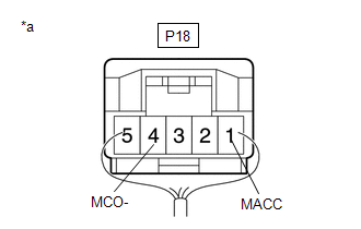
(b) Disconnect the P18 telephone microphone assembly connector.
(c) Measure the resistance according to the value(s) in the table below.
Standard Resistance:
| Tester Connection | Condition | Specified Condition |
|---|---|---|
| G128-5 (MCVD) - P18-1 (MACC) | Always | Below 1 Ω |
| G128-6 (MCI+) - P18-2 (MCO+) | Always | Below 1 Ω |
| G128-7 (MCI-) - P18-4 (MCO-) | Always | Below 1 Ω |
| G128-23 (SGND) - Body ground | Always | 10 kΩ or higher |
| G128-5 (MCVD) or P18-1 (MACC) - Body ground | Always | 10 kΩ or higher |
| G128-6 (MCI+) or P18-2 (MCO+) - Body ground | Always | 10 kΩ or higher |
| G128-7 (MCI-) or P18-4 (MCO-) - Body ground | Always | 10 kΩ or higher |
| NG | | REPAIR OR REPLACE HARNESS OR CONNECTOR |
|
| 3. | CHECK DCM (TELEMATICS TRANSCEIVER) (TELEPHONE MICROPHONE ASSEMBLY POWER SOURCE) |
| (a) Remove the telephone microphone assembly but do not disconnect the connectors. Click here |
|
(b) Measure the voltage and resistance according to the value(s) in the table below.
Standard Voltage:
| Tester Connection | Switch Condition | Specified Condition |
|---|---|---|
| P18-1 (MACC) - Body ground | Engine switch on (ACC) | 4 to 6 V |
Standard Resistance:
| Tester Connection | Condition | Specified Condition |
|---|---|---|
| P18-4 (MCO-) - Body ground | Always | Below 1 Ω |
| OK | | REPLACE TELEPHONE MICROPHONE ASSEMBLY |
|
| 4. | REPLACE DCM (TELEMATICS TRANSCEIVER) |
(a) Replace the DCM (telematics transceiver) with a new one.
Click here
NOTICE:
- The engine switch must be off
- Do not exchange the DCM (telematics transceiver) with one from another vehicle.
| NEXT | | PERFORM DCM ACTIVATION |
READ NEXT:
 Customize Parameters
CUSTOMIZE PARAMETERS CUSTOMIZE TELEMATICS SYSTEM (a) Customizing with the Techstream. NOTICE:
When the customer requests a change in a function, first make sure that the function can be customized.
Data List / Active Test
DATA LIST / ACTIVE TEST DATA LIST NOTICE: In the table below, the values listed under "Normal Condition" are reference values. Do not depend solely on these reference values when deciding whether a pa
Dcm Activation
DCM ACTIVATION HINT: If the DCM (telematics transceiver) has been replaced, it is necessary to perform the Register Vehicle Information procedure. DCM ACTIVATION (a) Connect the Techstream to the DLC3
SEE MORE:
How To Proceed With Troubleshooting
CAUTION / NOTICE / HINT HINT:
Before performing troubleshooting for the front radar sensor system, perform troubleshooting for the pre-collision system.
Click here
*: Use the Techstream.
PROCEDURE 1. VEHICLE BROUGHT TO WORKSHOP
NEXT 2. PRE-CHECK (a) Measu
Sliding Roof does not Move by Operating Sliding Roof Control Switch
DESCRIPTION The sliding roof ECU (sliding roof drive gear sub-assembly) receives slide and tilt signals and operates its built-in motor when the sliding roof switch (map light sub-assembly) is operated. WIRING DIAGRAM CAUTION / NOTICE / HINT NOTICE:
Inspect the fuses for circuits related to this
