Lexus ES: Inspection
INSPECTION
PROCEDURE
1. INSPECT STARTER ASSEMBLY
CAUTION:
As a large electric current passes through the cable during this inspection, a thick cable must be used. If not, the cable may become hot and cause injury.
NOTICE:
Perform each of the following tests within 3 to 5 seconds to prevent the coil from burning out.
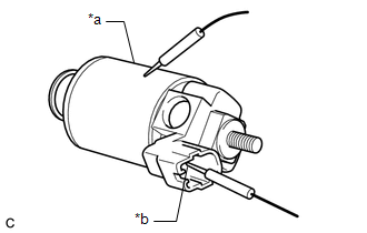
(a) Perform a pull-in test.
(1) Connect a battery to the magnet starter switch assembly as shown in the illustration. Check that the clutch pinion gear moves outward.
If the clutch pinion gear does not move outward, replace the magnet starter switch assembly.
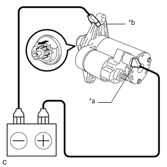
| *a | Terminal 50 |
| *b | Starter Body |
.png) | Moves outward |
(b) Perform a return test.
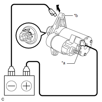
| *a | Terminal 50 |
| *b | Starter Body |
| | Disconnect |
.png) | Returns inward |
(1) While maintaining the battery connections of the pull-in test, disconnect the negative (-) lead from the starter body. Check that the clutch pinion gear returns inward.
If the clutch pinion gear does not return inward, replace the magnet starter switch assembly.
(c) Perform a no-load performance test.
(1) Secure the starter assembly in a vise between aluminum plates.
NOTICE:
Ensure that the starter assembly is secured in the vise to prevent it from falling out.
(2) Connect the battery and an ammeter to the starter assembly as shown in the illustration.
NOTICE:
Do not allow any lead to get caught as the clutch pinion gear operates.
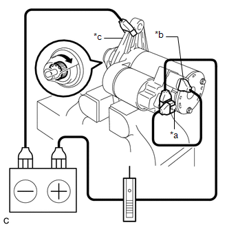
| *a | Terminal 30 |
| *b | Terminal 50 |
| *c | Starter Body |
| | Rotates |
(3) Check that the starter assembly operates smoothly and steadily while the clutch pinion gear is moving outward.
Measure the current according to the value(s) in the table below.
Standard Current:
| Tester Connection | Condition | Specified Condition |
|---|---|---|
| Battery positive (+) terminal - Terminal 30 - Terminal 50 | 11.5 V | Below 90 A |
If the result is not as specified, repair or replace the starter assembly.
2. INSPECT MAGNET STARTER SWITCH ASSEMBLY
| (a) Check the plunger. (1) Push in the plunger and check that it returns quickly to its original position. NOTICE: To avoid damaging the inside of the magnet starter switch assembly, do not release the plunger quickly. If the plunger does not operate as specified, replace the magnet starter switch assembly. |
|
| (b) Check the holding coil for an open circuit. (1) Measure the resistance according to the value(s) in the table below. Standard Resistance:
If the result is not as specified, replace the magnet starter switch assembly. |
|
3. INSPECT STARTER ARMATURE ASSEMBLY
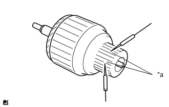
(a) Check the commutator appearance.
If the surface is dirty or burnt, restore it with sandpaper (400-grit) or on a lathe.
| (b) Check the commutator for an open circuit. (1) Measure the resistance according to the value(s) in the table below. Standard Resistance:
If the result is not as specified, replace the starter armature assembly. |
|
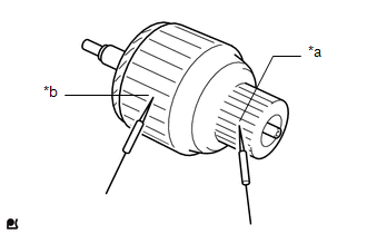
| (c) Check the commutator for a short circuit. (1) Measure the resistance according to the value(s) in the table below. Standard Resistance:
If the result is not as specified, replace the starter armature assembly. |
|
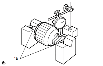
| (d) Check the commutator for runout. (1) Place the armature shaft on V-blocks. (2) Using a dial indicator, measure the runout. Maximum Runout: 0.05 mm (0.00197 in.) If the runout is greater than the maximum, replace the starter armature assembly. |
|
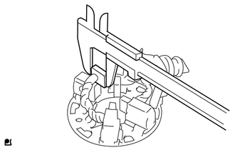
| (e) Using a vernier caliper, measure the commutator diameter. Standard Diameter: 25.0 mm (0.984 in.) Minimum Diameter: 24.0 mm (0.945 in.) If the diameter is less than the minimum, replace the starter armature assembly. |
|
| (f) Check that the undercut portion between the segments is free of foreign matter and measure its depth. Standard Undercut Depth: 0.7 mm (0.0276 in.) Minimum Undercut Depth: 0.2 mm (0.00787 in.) If the undercut depth is less than the minimum, replace the starter armature assembly. |
|

4. INSPECT STARTER BRUSH HOLDER ASSEMBLY
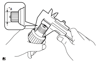
(a) Check the brush length.
| (1) Using a vernier caliper, measure the brush length. Standard Length: 11.6 mm (0.457 in.) Minimum Length: 7.6 mm (0.299 in.) If the length is less than the minimum, replace the starter brush holder assembly. |
|
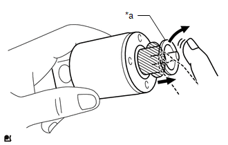
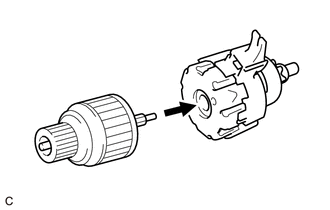
5. INSPECT STARTER CENTER BEARING CLUTCH SUB-ASSEMBLY
| (a) Install the starter armature assembly to the starter center bearing clutch sub-assembly. |
|
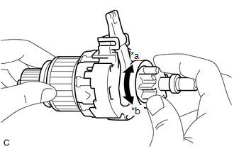
| (b) Hold the starter armature assembly, rotate the clutch pinion gear clockwise, and check that it turns freely. Try to rotate the clutch pinion gear counterclockwise and check that it locks. If the clutch pinion gear does not operate as specified, replace the starter center bearing clutch sub-assembly. |
|
READ NEXT:
 Reassembly
REASSEMBLY PROCEDURE 1. INSTALL STARTER CENTER BEARING CLUTCH SUB-ASSEMBLY (a) Apply high-temperature grease to the pinion drive lever. High-temperature Grease HINT: Apply approximately 0.1
Installation
INSTALLATION PROCEDURE 1. INSTALL STARTER ASSEMBLY (a) Install the starter assembly to the cylinder block sub-assembly with the 2 bolts. Torque: 46 N·m {469 kgf·cm, 34 ft·lbf} (b) Connect the No.
Starting System
Parts LocationPARTS LOCATION ILLUSTRATION *1 STARTER ASSEMBLY *2 ECM *3 PARK/NEUTRAL POSITION SWITCH ASSEMBLY *4 ENGINE ROOM RELAY BLOCK AND JUNCTION BLOCK ASSEMBLY - ST RELAY - S
SEE MORE:
Initialization
INITIALIZATION NOTICE:
The necessary procedures (adjustment, calibration, initialization or registration) that must be performed after parts are removed and installed, or replaced during headlight ECU sub-assembly LH removal/installation are shown below. for LED Type Turn Signal Light Replaced
Lost Communication with Blind Spot Monitor Slave Module (U0232,U0233)
DESCRIPTION This DTC is stored when the blind spot monitor sensor LH judges that there is a communication problem with the blind spot monitor sensor RH. DTC No. Detection Item DTC Detection Condition Trouble Area U0232 Lost Communication with Blind Spot Monitor Slave Module The clea
