Lexus ES: Starting System
Parts Location
PARTS LOCATION
ILLUSTRATION
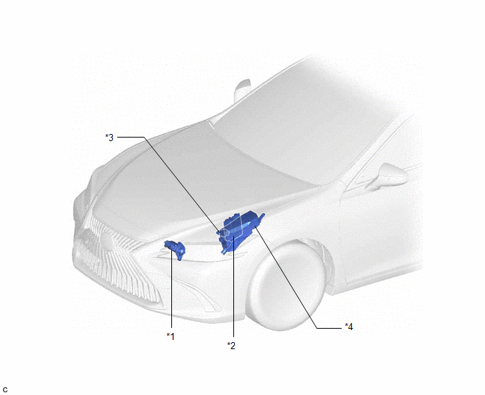
| *1 | STARTER ASSEMBLY | *2 | ECM |
| *3 | PARK/NEUTRAL POSITION SWITCH ASSEMBLY | *4 | ENGINE ROOM RELAY BLOCK AND JUNCTION BLOCK ASSEMBLY - ST RELAY - ST NO. 1 FUSE - FL MAIN FUSE |
ILLUSTRATION
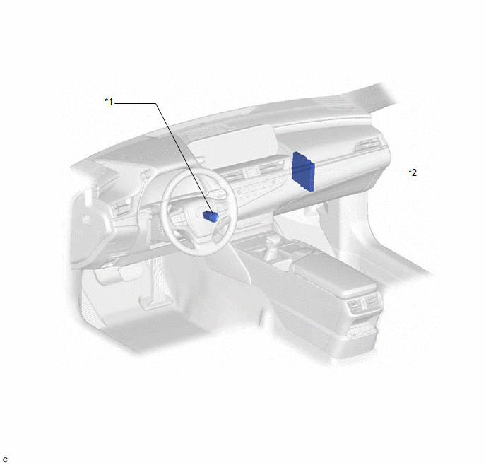
| *1 | ENGINE SWITCH | *2 | CERTIFICATION ECU (SMART KEY ECU ASSEMBLY) |
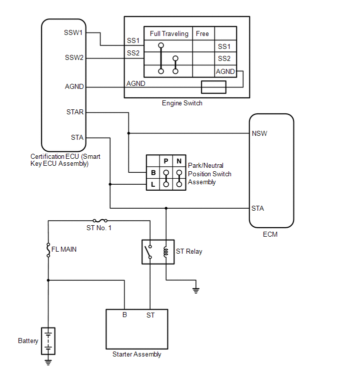
System Diagram
SYSTEM DIAGRAM
READ NEXT:
 Coolant
ComponentsCOMPONENTS ILLUSTRATION *1 RADIATOR CAP SUB-ASSEMBLY *2 RADIATOR DRAIN COCK PLUG *3 NO. 1 ENGINE UNDER COVER - - ReplacementREPLACEMENT CAUTION / NOTICE / HINT CAUTI
SEE MORE:
Removal
REMOVAL CAUTION / NOTICE / HINT The necessary procedures (adjustment, calibration, initialization or registration) that must be performed after parts are removed and installed, or replaced during tilt and telescopic switch removal/installation are shown below. Necessary Procedures After Parts Remove
Parts Location
PARTS LOCATION ILLUSTRATION *1 FRONT DOOR COURTESY LIGHT SWITCH ASSEMBLY (for LH) *2 FRONT DOOR COURTESY LIGHT SWITCH ASSEMBLY (for RH) *3 ROOF SUNSHADE ECU (SLIDING ROOF DRIVE GEAR ASSEMBLY) *4 SLIDING ROOF ECU (SLIDING ROOF DRIVE GEAR ASSEMBLY) *5 COMBINATION METER ASSEMB
© 2016-2026 Copyright www.lexguide.net
