Lexus ES: Reassembly
REASSEMBLY
PROCEDURE
1. INSTALL STARTER CENTER BEARING CLUTCH SUB-ASSEMBLY
(a) Apply high-temperature grease to the pinion drive lever.
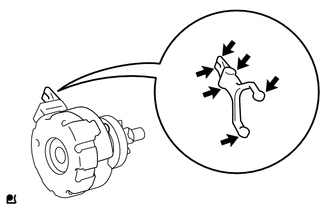
.png) | High-temperature Grease |
HINT:
Apply approximately 0.1 g of high-temperature grease to each section.
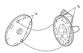
| (b) Align the cutout of the starter drive housing assembly with the protrusion of the starter center bearing clutch sub-assembly and install the starter center bearing clutch sub-assembly. |
|
| (c) Install the rubber seal to the starter drive housing assembly. |
|
.png)
2. INSTALL STARTER BRUSH HOLDER ASSEMBLY
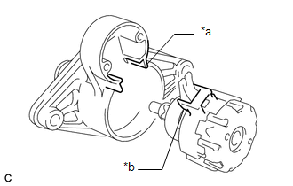
| (a) Install the starter commutator end frame assembly to the starter brush holder assembly as shown in the illustration. HINT: If the parts are not aligned correctly, the through bolt cannot be attached. |
|
| (b) Spread the brushes on the starter brush holder assembly, and install the starter armature assembly to the starter brush holder assembly. |
|
3. INSTALL STARTER ARMATURE ASSEMBLY
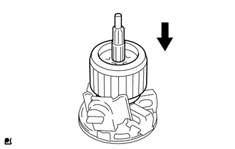
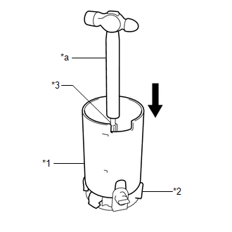
| (a) Install the starter yoke assembly while holding down the starter armature assembly and starter brush holder assembly with the handle of a hammer. HINT: The starter armature assembly will be attracted by the magnetic field of the starter yoke assembly. Hold the starter armature assembly with the handle of the hammer. |
|
4. INSTALL STARTER YOKE ASSEMBLY
| (a) Align the cutout of the starter yoke assembly with the protrusion of the starter center bearing clutch sub-assembly. |
|
| (b) Install the starter yoke assembly with the 3 through bolts. Torque: 3.0 N·m {31 kgf·cm, 27 in·lbf} |
|
.png)
5. INSTALL MAGNET STARTER SWITCH ASSEMBLY
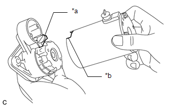
| (a) Hang the hook of the magnet starter switch assembly on the pinion drive lever. |
|
.png)
| (b) Push down the rear of the magnet starter switch assembly and connect it to terminal C. NOTICE:
|
|
.png)
| (c) Install the magnet starter switch assembly with the 2 bolts. Torque: 3.0 N·m {31 kgf·cm, 27 in·lbf} |
|
.png)
READ NEXT:
 Installation
INSTALLATION PROCEDURE 1. INSTALL STARTER ASSEMBLY (a) Install the starter assembly to the cylinder block sub-assembly with the 2 bolts. Torque: 46 N·m {469 kgf·cm, 34 ft·lbf} (b) Connect the No.
Starting System
Parts LocationPARTS LOCATION ILLUSTRATION *1 STARTER ASSEMBLY *2 ECM *3 PARK/NEUTRAL POSITION SWITCH ASSEMBLY *4 ENGINE ROOM RELAY BLOCK AND JUNCTION BLOCK ASSEMBLY - ST RELAY - S
SEE MORE:
Headlight Swivel Motor LH (B2412,B2413,B2417,B2418)
DESCRIPTION The headlight ECU sub-assembly LH sends automatic headlight beam level control signals to each headlight swivel motor and headlight leveling motor via LIN communication. Each headlight ECU sub-assembly and headlight swivel motor and headlight leveling motor communicate via LIN communicat
Installation
INSTALLATION CAUTION / NOTICE / HINT HINT:
Use the same procedure for the RH side and LH side.
The following procedure is for the LH side.
PROCEDURE 1. INSTALL FRONT DOOR FRONT LOWER FRAME UPPER COVER (a) Engage the 2 guides. (b) Install the front door front lower frame upper cover with the
