Lexus ES: Installation
Lexus ES (XZ10) Service Manual / Engine & Hybrid System / A25a-fks (starting) / Starter / Installation
INSTALLATION
PROCEDURE
1. INSTALL STARTER ASSEMBLY
(a) Install the starter assembly to the cylinder block sub-assembly with the 2 bolts.
Torque:
46 N·m {469 kgf·cm, 34 ft·lbf}
(b) Connect the No. 2 engine wire to terminal 30 with the nut.
Torque:
9.8 N·m {100 kgf·cm, 87 in·lbf}
(c) Close the terminal cap.
(d) Connect the starter assembly connector.
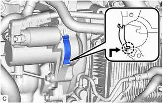
2. INSTALL FLYWHEEL HOUSING SIDE COVER
| (a) Align the protrusion with the cylinder block sub-assembly and engage the claw as shown in the illustration to install the flywheel housing side cover. NOTICE:
|
|
3. INSTALL FRONT ENGINE MOUNTING INSULATOR
Click here .gif)
4. CONNECT CABLE TO NEGATIVE BATTERY TERMINAL
Click here
READ NEXT:
 Starting System
Parts LocationPARTS LOCATION ILLUSTRATION *1 STARTER ASSEMBLY *2 ECM *3 PARK/NEUTRAL POSITION SWITCH ASSEMBLY *4 ENGINE ROOM RELAY BLOCK AND JUNCTION BLOCK ASSEMBLY - ST RELAY - S
Coolant
ComponentsCOMPONENTS ILLUSTRATION *1 RADIATOR CAP SUB-ASSEMBLY *2 RADIATOR DRAIN COCK PLUG *3 NO. 1 ENGINE UNDER COVER - - ReplacementREPLACEMENT CAUTION / NOTICE / HINT CAUTI
SEE MORE:
Data List / Active Test
DATA LIST / ACTIVE TEST NOTICE:
In the table below, the values listed under "Normal Condition" are reference values. Do not depend solely on these reference values when deciding whether a part is faulty or not.
When diagnosing symptoms such as hesitation, rough idle, or other small symptoms usi
Installation
INSTALLATION CAUTION / NOTICE / HINT NOTICE: This procedure includes the installation of small-head bolts. Refer to Small-Head Bolts of Basic Repair Hint to identify the small-head bolts. Click here PROCEDURE 1. INSTALL ENGINE BALANCER ASSEMBLY Click here 2. INSTALL STIFFENING CRANKCASE ASSEM
© 2016-2026 Copyright www.lexguide.net
