Lexus ES: Components
COMPONENTS
ILLUSTRATION
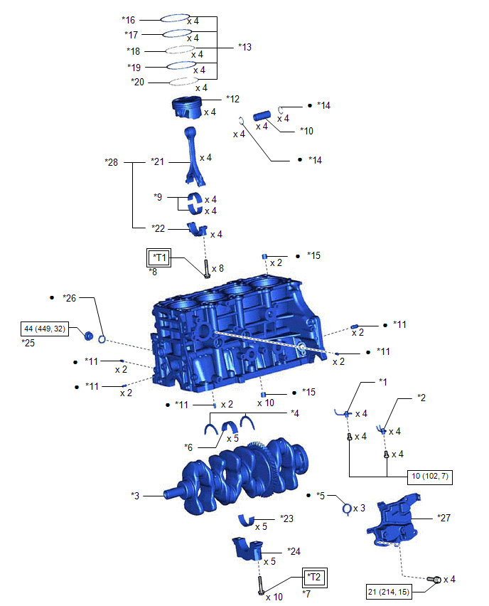
| *1 | NO. 1 OIL NOZZLE SUB-ASSEMBLY | *2 | NO. 2 OIL NOZZLE SUB-ASSEMBLY |
| *3 | CRANKSHAFT | *4 | CRANKSHAFT THRUST WASHER |
| *5 | OIL SEPARATOR GASKET | *6 | CRANKSHAFT BEARING |
| *7 | CRANKSHAFT BEARING CAP SET BOLT | *8 | CONNECTING ROD BOLT |
| *9 | CONNECTING ROD BEARING | *10 | PISTON PIN |
| *11 | STRAIGHT PIN | *12 | PISTON |
| *13 | PISTON RING SET | *14 | PISTON PIN HOLE SNAP RING |
| *15 | RING PIN | *16 | NO. 1 COMPRESSION RING |
| *17 | NO. 2 COMPRESSION RING | *18 | UPPER SIDE RAIL |
| *19 | OIL RING EXPANDER | *20 | LOWER SIDE RAIL |
| *21 | CONNECTING ROD | *22 | CONNECTING ROD CAP |
| *23 | NO. 2 CRANKSHAFT BEARING | *24 | CRANKSHAFT BEARING CAP |
| *25 | CYLINDER BLOCK WITH HEAD STRAIGHT SCREW PLUG | *26 | GASKET |
| *27 | NO. 1 VENTILATION CASE | *28 | CONNECTING ROD SUB-ASSEMBLY |
.png) | Tightening torque for "Major areas involving basic vehicle performance such as moving/turning/stopping": N*m (kgf*cm, ft.*lbf) | .png) | N*m (kgf*cm, ft.*lbf): Specified torque |
| ● | Non-reusable part | - | - |
| *T1 | 1st: 38 (387, 28) 2nd: Turn 90° | *T2 | 1st: 61 (622, 45) 2nd: Turn 90° |
READ NEXT:
 Inspection
INSPECTION PROCEDURE 1. INSPECT CYLINDER BLOCK FOR WARPAGE (a) Using a precision straightedge and feeler gauge, check the surface which contacts the cylinder head gasket for warpage. Maximum Warpag
Replacement
REPLACEMENT PROCEDURE 1. REPLACE RING PIN NOTICE: It is not necessary to remove the ring pins unless they are being replaced. (a) Remove the 12 ring pins. (b) Using a plastic hammer, install 12 new ri
Reassembly
REASSEMBLY PROCEDURE 1. INSTALL NO. 2 OIL NOZZLE SUB-ASSEMBLY (a) Using a 5 mm hexagon wrench, install the 4 No. 2 oil nozzle sub-assemblies to the cylinder block sub-assembly with the 4 bolts. Tor
SEE MORE:
Installation
INSTALLATION PROCEDURE 1. INSTALL DCM (TELEMATICS TRANSCEIVER) 2. INSTALL NO. 1 TELEPHONE BRACKET (a) Install the No. 1 telephone bracket with the screw. 3. INSTALL TELEPHONE BRACKET (a) Install the telephone bracket with the screw. 4. INSTALL DCM (TELEMATICS TRANSCEIVER) WITH BRACKET (a) Connect ea
Tire Pressure Warning Light Circuit
DESCRIPTION If the tire pressure warning ECU and receiver detects any problems, the tire pressure warning light blinks for 1 minute then illuminates, and tire pressure monitoring is disabled at the same time. At this time, the ECU stores a DTC in memory. The tire pressure warning ECU and receiver se
