Lexus ES: Inspection
INSPECTION
PROCEDURE
1. INSPECT FRONT DRIVE SHAFT ASSEMBLY
| (a) Check that there is no excessive play in the radial direction of the outboard joint. |
|
.png)
(b) Check that the inboard joint slides smoothly in the thrust direction.
(c) Check that there is no excessive play in the radial direction of the inboard joint.
(d) Check the boots for damage.
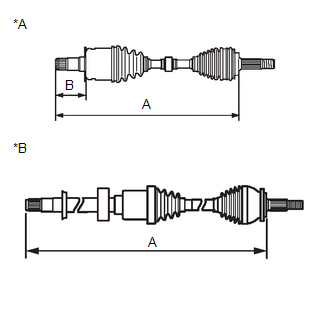
| (e) Check whether the drive shaft dimension (A) and (B) are within specification. NOTICE: Keep the drive shaft assembly level during inspection. Dimension (A):
Dimension (B):
|
|
READ NEXT:
 Installation
INSTALLATION PROCEDURE 1. INSTALL FRONT DRIVE SHAFT HOLE SNAP RING (a) Install a new front drive shaft hole snap ring. NOTICE: Face the end gap of the front drive shaft hole snap ring downward. 2. INS
Reassembly
REASSEMBLY PROCEDURE 1. INSTALL FRONT DRIVE SHAFT BEARING (for RH Side) (a) Using SST, a steel plate and a press, install a new front drive shaft bearing. SST: 09527-10011 NOTICE: The bearing shoul
Removal
REMOVAL CAUTION / NOTICE / HINT The necessary procedures (adjustment, calibration, initialization, or registration) that must be performed after parts are removed and installed, or replaced during fro
SEE MORE:
Lost Communication with Cruise Control Module Missing Message (U010487,U012287,U029387)
DESCRIPTION The hybrid vehicle control ECU communicates with each sensor and ECU via CAN communication. If any malfunction is detected in a CAN communication circuit, one or more CAN communication system DTCs are stored. DTC No. Detection Item DTC Detection Condition Trouble Area MIL DT
Removal
REMOVAL CAUTION / NOTICE / HINT The necessary procedures (adjustment, calibration, initialization or registration) that must be performed after parts are removed and installed, or replaced during front crankshaft oil seal removal/installation are shown below. Necessary Procedure After Parts Removed/
© 2016-2026 Copyright www.lexguide.net
