Lexus ES: Removal
REMOVAL
CAUTION / NOTICE / HINT
The necessary procedures (adjustment, calibration, initialization, or registration) that must be performed after parts are removed and installed, or replaced during front drive shaft assembly removal/installation are shown below.
Necessary Procedures After Parts Removed/Installed/Replaced| Replaced Part or Performed Procedure | Necessary Procedure | Effect/Inoperative Function when Necessary Procedure not Performed | Link |
|---|---|---|---|
| Front wheel alignment adjustment |
|
| |
| Automatic transaxle fluid | ATF thermal degradation estimate reset | The value of the Data List item "ATF Thermal Degradation Estimate" is not estimated correctly. | |
PROCEDURE
1. REMOVE FRONT WHEELS
Click here .gif)
2. REMOVE FRONT WHEEL OPENING EXTENSION PAD RH
Click here
3. REMOVE FRONT WHEEL OPENING EXTENSION PAD LH
Click here
4. REMOVE NO. 1 ENGINE UNDER COVER
Click here
5. REMOVE NO. 2 ENGINE UNDER COVER ASSEMBLY
Click here
6. REMOVE FRONT FENDER APRON SEAL LH
Click here
7. REMOVE FRONT FENDER APRON SEAL RH
Click here
8. DRAIN AUTOMATIC TRANSAXLE FLUID
Click here
9. DRAIN TRANSFER OIL
Click here
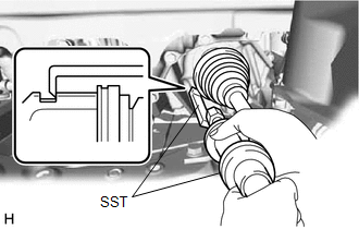
10. REMOVE FRONT AXLE SHAFT NUT
| (a) Using SST and a hammer, release the staked part of the front axle shaft nut. SST: 09930-00010 NOTICE: Fully loosen the staked part of the front axle shaft nut, otherwise the threads of the drive shaft may be damaged. |
|
.png)
(b) While applying the brakes, remove the front axle shaft nut.
11. SEPARATE FRONT SPEED SENSOR
Click here
12. SEPARATE TIE ROD ASSEMBLY
Click here
13. SEPARATE FRONT STABILIZER LINK ASSEMBLY
Click here
14. SEPARATE FRONT LOWER NO. 1 SUSPENSION ARM SUB-ASSEMBLY
Click here
15. SEPARATE FRONT DRIVE SHAFT ASSEMBLY
Click here
16. REMOVE FRONT DRIVE SHAFT ASSEMBLY LH
| (a) Using SST, remove the front drive shaft assembly LH. SST: 09520-01011 SST: 09520-20010 09521-02010 09521-02040 09521-02060 NOTICE:
|
|
17. REMOVE FRONT DRIVE SHAFT ASSEMBLY RH
| (a) Separate the drive shaft bearing bracket hole snap ring from the drive shaft bearing bracket. |
|
.png)
(b) Remove the No. 1 drive shaft bearing bracket setting bolt and front drive shaft assembly RH from the transfer assembly.
NOTICE:
- Do not damage the transfer case oil seal RH.
- Do not damage the front axle inboard joint boot.
- Do not drop the front drive shaft assembly RH.
HINT:
If it is difficult to disengage the fitting, tap the end of the front drive inboard joint assembly with a brass bar and a hammer.
(c) Remove the drive shaft bearing bracket hole snap ring from the front drive shaft assembly RH.
18. REMOVE FRONT DRIVE SHAFT HOLE SNAP RING
| (a) Using a screwdriver, remove the front drive shaft hole snap ring. |
|
.png)
READ NEXT:
 Components
COMPONENTS ILLUSTRATION *1 NO. 1 ENGINE UNDER COVER *2 FRONT FENDER APRON SEAL LH *3 FRONT FENDER APRON SEAL RH *4 FRONT WHEEL OPENING EXTENSION PAD LH *5 FRONT WHEEL OPENING
Disassembly
DISASSEMBLY CAUTION / NOTICE / HINT HINT:
Use the same procedure for the RH side and LH side.
The following procedure is for the LH side.
PROCEDURE 1. SEPARATE FRONT NO. 2 AXLE INBOARD JOINT B
SEE MORE:
Reassembly
REASSEMBLY PROCEDURE 1. INSTALL REAR BUMPER REINFORCEMENT (a) Install the rear bumper reinforcement with the 6 bolts. Torque: 35 N·m {357 kgf·cm, 26 ft·lbf} 2. INSTALL REAR BUMPER PROTECTOR INSERT LH (a) Engage the guide and claw to install the rear bumper protector insert LH.
Open in IG Circuit (B242E)
DESCRIPTION The headlight ECU sub-assembly operates using the power source voltage input from the IG terminal and ECUB terminal. The IG terminal power source voltage is supplied by turning the IG1-NO. 1 relay to ON. The headlight ECU sub-assembly receives power switch on (IG) signals from the main b
