Lexus ES: Installation
INSTALLATION
PROCEDURE
1. INSTALL FRONT DRIVE SHAFT HOLE SNAP RING
(a) Install a new front drive shaft hole snap ring.
NOTICE:
Face the end gap of the front drive shaft hole snap ring downward.
2. INSTALL FRONT DRIVE SHAFT ASSEMBLY LH
(a) Coat the snap ring of the front drive inboard joint assembly with MP grease.
(b) Coat the splines of the front drive inboard joint assembly with Toyota genuine ATF WS.
(c) Coat the lip of the front drive shaft oil seal LH with MP grease and Toyota genuine oil seal side lip grease as shown in the illustration.
HINT:
Apply a light coat of MP grease and Toyota genuine oil seal side lip grease to the entire circumference of the front drive shaft oil seal LH.
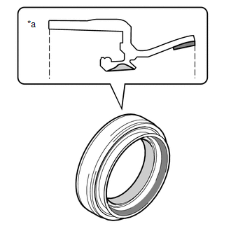
| *a | Cross Section of Front Drive Shaft Oil Seal LH |
.png) | MP Grease |
.png) | Toyota Genuine Oil Seal Side Lip Grease |
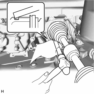
| (d) Align the inboard joint splines, and using a brass bar and a hammer, install the front drive shaft assembly LH. NOTICE:
HINT: Confirm whether the drive shaft is securely driven in by checking the reaction force and sound. |
|
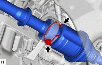
(e) Apply 0.1 to 0.3 g (0.00353 to 0.0105 oz) of Toyota Body Grease W to each of the 4 areas shown in the illustration.
.png)
.png) | Toyota Body Grease W |
| (f) Align the matchmarks and install the front drive shaft assembly LH to the front axle hub sub-assembly. NOTICE:
|
|
.png)
3. INSTALL FRONT DRIVE SHAFT ASSEMBLY RH
(a) Coat the lip of the transfer case oil seal RH with MP grease.
(b) Coat the splines of the front drive inboard joint assembly with Toyota genuine ATF WS.
(c) Install a new drive shaft bearing bracket hole snap ring to the front drive shaft assembly RH.
(d) Align the inboard joint splines, and securely insert the front drive shaft assembly RH.
NOTICE:
- Do not damage the transfer case oil seal RH.
- Do not damage the front axle inboard joint boot.
- When inserting the front drive shaft assembly RH, keep it level.
| (e) Install the drive shaft bearing bracket hole snap ring and a new No. 1 drive shaft bearing bracket setting bolt. Torque: 32.4 N·m {330 kgf·cm, 24 ft·lbf} |
|
(f) Apply 0.1 to 0.3 g (0.00353 to 0.0105 oz) of Toyota Body Grease W to each of the 4 areas shown in the illustration.
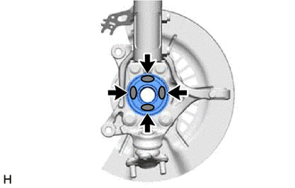
| | Toyota Body Grease W |
| (g) Align the matchmarks and install the front drive shaft assembly RH to the front axle hub sub-assembly. NOTICE:
|
|
.png)
4. CONNECT FRONT LOWER NO. 1 SUSPENSION ARM SUB-ASSEMBLY
Click here .gif)
5. INSTALL FRONT STABILIZER LINK ASSEMBLY
Click here
6. CONNECT TIE ROD ASSEMBLY
Click here
7. INSTALL FRONT SPEED SENSOR
Click here
8. INSTALL FRONT AXLE SHAFT NUT
(a) Clean the threaded parts on the front drive shaft assembly and a new front axle shaft nut using non-residue solvent.
NOTICE:
- Make sure to perform this work even when using a new front drive shaft assembly.
- Keep the threaded parts free of oil and foreign matter.
| (b) Using a 30 mm deep socket wrench, install the front axle shaft nut. Torque: 294 N·m {2998 kgf·cm, 217 ft·lbf} HINT: Depress the brake pedal to prevent the drive shaft from rotating. |
|
.png)
(c) Using a chisel and hammer, stake the front axle shaft nut.
9. ADD AUTOMATIC TRANSAXLE FLUID
Click here
10. INSPECT FOR AUTOMATIC TRANSAXLE FLUID LEAK
11. ADD TRANSFER OIL
Click here
12. INSPECT FOR TRANSFER OIL LEAK
13. INSTALL FRONT WHEELS
Click here
14. INSPECT AND ADJUST FRONT WHEEL ALIGNMENT
Click here
15. INSTALL FRONT FENDER APRON SEAL LH
Click here
16. INSTALL FRONT FENDER APRON SEAL RH
Click here
17. INSTALL NO. 2 ENGINE UNDER COVER ASSEMBLY
Click here
18. INSTALL NO. 1 ENGINE UNDER COVER
Click here
19. INSTALL FRONT WHEEL OPENING EXTENSION PAD LH
Click here
20. INSTALL FRONT WHEEL OPENING EXTENSION PAD RH
Click here
21. CHECK FOR SPEED SENSOR SIGNAL
Click here
READ NEXT:
 Reassembly
REASSEMBLY PROCEDURE 1. INSTALL FRONT DRIVE SHAFT BEARING (for RH Side) (a) Using SST, a steel plate and a press, install a new front drive shaft bearing. SST: 09527-10011 NOTICE: The bearing shoul
Removal
REMOVAL CAUTION / NOTICE / HINT The necessary procedures (adjustment, calibration, initialization, or registration) that must be performed after parts are removed and installed, or replaced during fro
SEE MORE:
Components
COMPONENTS ILLUSTRATION *1 FUEL PUMP ASSEMBLY *2 FUEL PUMP PROTECTOR *3 NO. 1 FUEL PIPE SUB-ASSEMBLY *4 NO. 2 FUEL TUBE SUB-ASSEMBLY *5 FUEL PUMP LIFTER ASSEMBLY *6 FUEL PUMP LIFTER GUIDE *7 FUEL PUMP SPACER GASKET *8 FUEL TUBE SUB-ASSEMBLY *9 O-RING -
Registration
REGISTRATION CAUTION / NOTICE / HINT PROCEDURE 1. VIN (VEHICLE IDENTIFICATION NUMBER) NOTICE: The Vehicle Identification Number (VIN) must be written to a replacement ECM. HINT: The VIN is a 17-digit alphanumeric vehicle identification number. The Techstream is required to register the VIN. (a) DESC
