Lexus ES: Reassembly
REASSEMBLY
PROCEDURE
1. INSTALL FRONT DRIVE SHAFT BEARING (for RH Side)
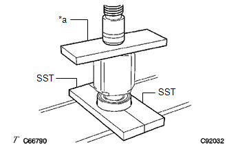
| (a) Using SST, a steel plate and a press, install a new front drive shaft bearing. SST: 09527-10011 NOTICE: The bearing should be completely installed. |
|
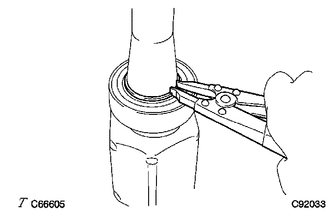
| (b) Using a snap ring expander, install a new drive shaft hole snap ring. NOTICE: Install the drive shaft hole snap ring securely. |
|
2. INSTALL FRONT DRIVE SHAFT DUST COVER RH (for RH Side)
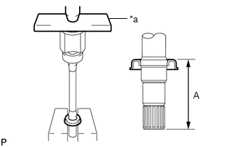
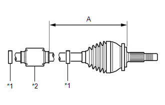
| (a) Using a steel plate and a press, install a new front drive shaft dust cover RH until the dimension (A) from the tip of the front drive inboard joint assembly to the front drive shaft dust cover RH meets the specification. Dimension (A): 296.7 to 297.3 mm (11.68 to 11.70 in.) NOTICE: Be careful not to damage the front drive shaft dust cover RH. |
|
3. INSTALL FRONT AXLE OUTBOARD JOINT BOOT
(a) Secure the drive shaft in a vise between aluminum plates.
NOTICE:
Do not overtighten the vise.
| (b) Wrap the splines of the front drive outboard joint shaft assembly with protective tape to prevent the boot from being damaged. |
|
.png)
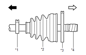
(c) Install new parts to the front drive outboard joint shaft assembly in the following order:
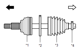
| *1 | Front Drive Outboard Joint Shaft Assembly |
| *2 | Front No. 2 Axle Outboard Joint Boot Clamp |
| *3 | Front Axle Outboard Joint Boot |
| *4 | Front Axle Outboard Joint Boot Clamp |
.png) | Outboard joint side |
.png) | Inboard joint side |
(1) Front No. 2 axle outboard joint boot clamp
(2) Front axle outboard joint boot
(3) Front axle outboard joint boot clamp
(d) Pack the joint portion of the front drive outboard joint shaft assembly and front axle outboard joint boot with grease.
Standard Grease Capacity:
95 to 115 g (3.36 to 4.05 oz)
(e) Install the front axle outboard joint boot to the front drive outboard joint shaft assembly groove.
NOTICE:
- Do not allow grease to adhere to the boot clamp track of the outboard joint boot.
- Keep the inside of the outboard joint boot free of foreign matter.
4. INSTALL FRONT NO. 2 AXLE OUTBOARD JOINT BOOT CLAMP
(a) Secure the drive shaft in a vise between aluminum plates.
NOTICE:
Do not overtighten the vise.
(b) Install the front No. 2 axle outboard joint boot clamp to the front axle outboard joint boot.
| (c) Place SST onto the front No. 2 axle outboard joint boot clamp, press it against the boot and slightly tighten SST. SST: 09521-24010 |
|
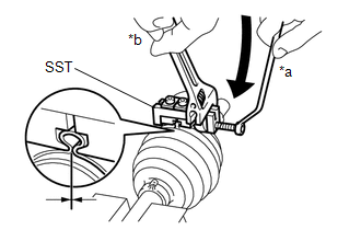
(d) Tighten SST so that the front No. 2 axle outboard joint boot clamp is pinched.
NOTICE:
Do not overtighten SST.
(e) Remove SST.
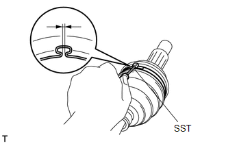
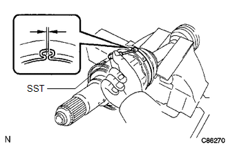
| (f) Using SST, measure the clearance of the front No. 2 axle outboard joint boot clamp. SST: 09240-00020 Clearance: 1.2 to 4.0 mm (0.0472 to 0.1575 in.) If the clearance is not as specified, retighten SST. |
|
5. INSTALL FRONT AXLE OUTBOARD JOINT BOOT CLAMP
(a) Secure the drive shaft in a vise between aluminum plates.
NOTICE:
Do not overtighten the vise.
(b) Install the front axle outboard joint boot clamp to the front axle outboard joint boot.
| (c) Place SST onto the front axle outboard joint boot clamp, press it against the boot and slightly tighten SST. SST: 09521-24010 |
|
.png)
(d) Tighten SST so that the front axle outboard joint boot clamp is pinched.
NOTICE:
Do not overtighten SST.
(e) Remove SST.
| (f) Using SST, measure the clearance of the front axle outboard joint boot clamp. SST: 09240-00020 Clearance: 1.2 to 4.0 mm (0.0472 to 0.1575 in.) If the clearance is not as specified, retighten SST. |
|
.png)
6. INSTALL FRONT DRIVE SHAFT DAMPER
| (a) Temporarily install the front drive shaft damper and 2 new front drive shaft damper clamps to the front drive outboard joint shaft assembly as shown in the illustration. |
|
(b) Set the dimension (A) as specified below.
Dimension (A):
223.4 to 227.4 mm (8.80 to 8.95 in.)
7. INSTALL FRONT DRIVE SHAFT DAMPER CLAMP
(a) Secure the drive shaft in a vise between aluminum plates.
NOTICE:
Do not overtighten the vise.
(b) Install the 2 front drive shaft damper clamps to the front drive shaft damper.
NOTICE:
Be sure to install the clamps in the correct position.
| (c) Using needle-nose pliers, install the 2 front drive shaft damper clamps as shown in the illustration. NOTICE:
|
|
.png)
8. INSTALL FRONT DRIVE INBOARD JOINT ASSEMBLY
(a) Install new parts to the front drive outboard joint shaft assembly in the following order:
| *1 | Front Axle Inboard Joint Boot Clamp |
| *2 | Front Axle Inboard Joint Boot |
| *3 | Front No. 2 Axle Inboard Joint Boot Clamp |
| *4 | Protective Tape |
| | Outboard Joint Side |
| | Inboard Joint Side |
(1) Front axle inboard joint boot clamp
(2) Front axle inboard joint boot
(3) Front No. 2 axle inboard joint boot clamp
(b) Secure the drive shaft in a vise between aluminum plates.
NOTICE:
Do not overtighten the vise.
(c) Remove the protective tape.
| (d) Align the matchmarks and install the tripod joint to the front drive outboard joint shaft assembly. NOTICE: Face the serrated side of the tripod joint outward and install it to the outboard joint end. |
|
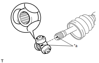
(e) Using a brass bar and a hammer, install the tripod joint to the front drive outboard joint shaft assembly.
NOTICE:
- Do not tap the rollers.
- Keep the tripod joint free of foreign matter.
- Make sure to install the tripod joint in the correct direction.
| (f) Using a snap ring expander, install a new shaft snap ring to the front drive outboard joint shaft assembly. |
|
.png)
(g) Pack the front drive inboard joint assembly and front axle inboard joint boot with grease.
Standard Grease Capacity:
170 to 190 g (6.00 to 6.70 oz)
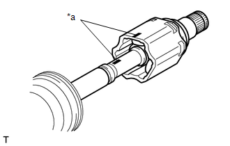
| (h) Align the matchmarks and install the front drive inboard joint assembly to the front drive outboard joint shaft assembly. |
|
9. INSTALL FRONT AXLE INBOARD JOINT BOOT
(a) Install the front axle inboard joint boot to the front drive inboard joint assembly.
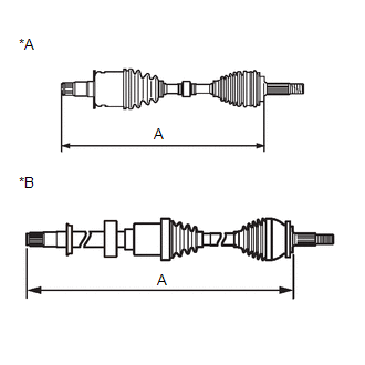
| (b) Check whether the dimension (A) of each drive shaft is within specification. Dimension (A):
|
|
10. INSTALL FRONT NO. 2 AXLE INBOARD JOINT BOOT CLAMP
(a) Secure the drive shaft in a vise between aluminum plates.
NOTICE:
Do not overtighten the vise.
(b) Install the front No. 2 axle inboard joint boot clamp to the front axle inboard joint boot.
| (c) Place SST onto the front No. 2 axle inboard joint boot clamp, press it against the boot and slightly tighten SST. SST: 09521-24010 |
|
(d) Tighten SST so that the front No. 2 axle inboard joint boot clamp is pinched.
NOTICE:
Do not overtighten SST.
(e) Remove SST.
| (f) Using SST, measure the clearance of the front No. 2 axle inboard joint boot clamp. SST: 09240-00020 Clearance: 1.2 to 4.0 mm (0.0472 to 0.1575 in.) If the clearance is not as specified, retighten SST. |
|
11. INSTALL FRONT AXLE INBOARD JOINT BOOT CLAMP
(a) Secure the drive shaft in a vise between aluminum plates.
NOTICE:
Do not overtighten the vise.
(b) Install the front axle inboard joint boot clamp to the front axle inboard joint boot.
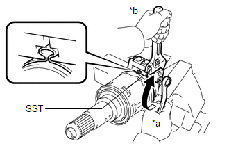
| (c) Place SST onto the front axle inboard joint boot clamp, press it against the boot and slightly tighten SST. SST: 09521-24010 |
|
.png)
(d) Tighten SST so that the front axle inboard joint boot clamp is pinched.
NOTICE:
Do not overtighten SST.
(e) Remove SST.
| (f) Using SST, measure the clearance of the front axle inboard joint boot clamp. SST: 09240-00020 Clearance: 1.2 to 4.0 mm (0.0472 to 0.1575 in.) If the clearance is not as specified, retighten SST. |
|
.png)
12. INSPECT FRONT DRIVE SHAFT ASSEMBLY
Click here .gif)
READ NEXT:
 Removal
REMOVAL CAUTION / NOTICE / HINT The necessary procedures (adjustment, calibration, initialization, or registration) that must be performed after parts are removed and installed, or replaced during fro
Components
COMPONENTS ILLUSTRATION *1 NO. 1 ENGINE UNDER COVER *2 FRONT FENDER APRON SEAL LH *3 FRONT FENDER APRON SEAL RH *4 FRONT WHEEL OPENING EXTENSION PAD LH *5 FRONT WHEEL OPENING
SEE MORE:
Terminals Of Ecu
TERMINALS OF ECU CLEARANCE WARNING ECU ASSEMBLY (a) Disconnect the N41 clearance warning ECU assembly connector. (b) Measure the voltage and resistance on the wire harness side connector according to the value(s) in the table below. Terminal No. (Symbol) Wiring Color Terminal Description C
Satellite Radio Broadcast cannot be Received
CAUTION / NOTICE / HINT NOTICE: Some satellite radio broadcasts require payment. A contract must be made between a satellite radio company and the user. If the contract expires, it will not be possible to listen to the broadcast. PROCEDURE 1. CHECK SURROUNDINGS (a) Check if the vehicle is i
