Lexus ES: Disassembly
DISASSEMBLY
CAUTION / NOTICE / HINT
NOTICE:
Before replacing the steering lock actuator assembly, refer to Registration.
for Gasoline Model: Click here .gif)
for HV Model: Click here
PROCEDURE
1. REMOVE STEERING LOCK ACTUATOR ASSEMBLY
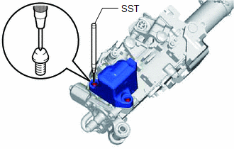
(a) Secure the steering column assembly in a vise between aluminum plates.
NOTICE:
Do not overtighten the vise.
| (b) Using SST, strike a punch mark for drilling in the center of the steering lock set bolt. SST: 09622-00010 NOTICE: When striking the punch mark, in order to prevent impact force from being applied to the steering lock actuator assembly, do not use a normal center punch. |
|
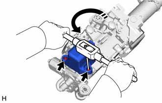
(c) Using a drill, drill a hole in the 2 steering lock set bolts and insert a screw extractor.
| (d) Using the screw extractor, remove the 2 steering lock set bolts and steering lock actuator assembly. |
|
2. REMOVE MULTIPLEX TILT AND TELESCOPIC ECU
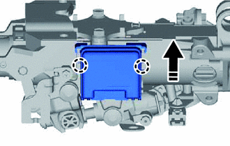
.png) | Remove in this direction |
(a) Disengage the 2 claws and remove the multiplex tilt and telescopic ECU.
READ NEXT:
 Inspection
INSPECTION PROCEDURE 1. INSPECT STEERING COLUMN ASSEMBLY (a) Check that the 2 bushings are securely installed to the steering column assembly. HINT: If the bushings are deformed, missing or damaged
Reassembly
REASSEMBLY PROCEDURE 1. INSTALL MULTIPLEX TILT AND TELESCOPIC ECU Install in this direction (a) Engage the 2 claws to install the multiplex tilt and telescopic ECU. 2. INSTALL STEERING LOCK
Installation
INSTALLATION PROCEDURE 1. ALIGN FRONT WHEELS FACING STRAIGHT AHEAD 2. INSTALL STEERING COLUMN ASSEMBLY NOTICE: Make sure that the wire harness is not interfering with the steering column assembly. (a)
SEE MORE:
Adjustment
ADJUSTMENT CAUTION / NOTICE / HINT NOTICE: Before adjusting the park/neutral position switch assembly, check that the shift lever is in N. PROCEDURE 1. SECURE VEHICLE (a) Fully apply the parking brake and chock a wheel. CAUTION:
Make sure to apply the parking brake and chock a wheel before perfor
Position Initialization Incomplete (B2343)
DESCRIPTION This DTC is stored when the sliding roof ECU (sliding roof drive gear assembly) has not been initialized. DTC No. Detection Item DTC Detection Condition Trouble Area B2343 Position Initialization Incomplete Sliding roof ECU (sliding roof drive gear assembly) has not been
