Lexus ES: Installation
INSTALLATION
PROCEDURE
1. ALIGN FRONT WHEELS FACING STRAIGHT AHEAD
2. INSTALL STEERING COLUMN ASSEMBLY
NOTICE:
Make sure that the wire harness is not interfering with the steering column assembly.
(a) Install the steering column assembly with the bolt and 2 nuts.
Torque:
36 N·m {367 kgf·cm, 27 ft·lbf}
(b) Connect each connector and engage each wire harness clamp to the steering column assembly.
3. INSTALL STEERING INTERMEDIATE SHAFT ASSEMBLY
(a) Align the matchmarks on the steering intermediate shaft assembly and steering column assembly.
| *a | Matchmark |
.png) | Install in this direction |
(b) Install the steering intermediate shaft assembly to the steering column assembly.
(c) Install the bolt.
Torque:
35 N·m {357 kgf·cm, 26 ft·lbf}
| (d) Tighten the clamp. |
|
.png)
4. INSTALL STEERING COLUMN HOLE COVER
(a) Install the steering column hole cover with the 2 clips.
(b) Install the clip.
(c) Return the floor carpet.
5. CONNECT STEERING INTERMEDIATE SHAFT ASSEMBLY
Click here .gif)
6. INSTALL FRONT WHEEL LH
Click here
7. INSTALL NO. 1 AIR DUCT SUB-ASSEMBLY
| (a) Engage the 3 claws to install a new No. 1 air duct sub-assembly. |
|
.png)
(b) Install the 2 bolts.
Torque:
9.8 N·m {100 kgf·cm, 87 in·lbf}
8. INSTALL LOWER NO. 1 INSTRUMENT PANEL AIRBAG ASSEMBLY
Click here
9. INSTALL TURN SIGNAL SWITCH ASSEMBLY WITH SPIRAL CABLE SUB-ASSEMBLY
NOTICE:
- Do not remove/install the spiral cable with sensor sub-assembly with the auxiliary battery connected and the engine switch (for Gasoline Model) or power switch (for HV Model) on (IG).
- Do not rotate the spiral cable with sensor sub-assembly without the steering wheel assembly installed, with the auxiliary battery connected and the engine switch (for Gasoline Model) or power switch (for HV Model) on (IG).
- Ensure that the steering wheel assembly is installed and aligned straight when inspecting the steering sensor.
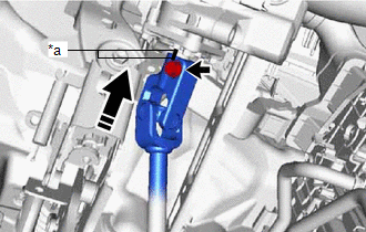
| (a) Using pliers, expand the clamp. |
|
(b) While holding the clamp expanded, install the turn signal switch assembly with spiral cable sub-assembly to the steering column assembly and engage the claw.
(c) Return the clamp to its original position.
(d) Connect the connectors to the turn signal switch assembly with spiral cable sub-assembly.
10. INSTALL UPPER STEERING COLUMN COVER
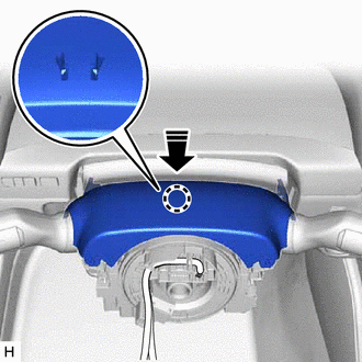
| (a) Engage the 2 claws and 4 clips to connect the upper steering column cover. |
|
.png)
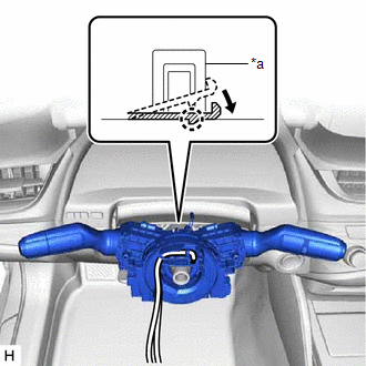
(b) Engage the claw to install the upper steering column cover.
| | Install in this direction |
11. INSTALL LOWER STEERING COLUMN COVER SUB-ASSEMBLY
| (a) Engage the 2 claws to install the lower steering column cover sub-assembly. |
|
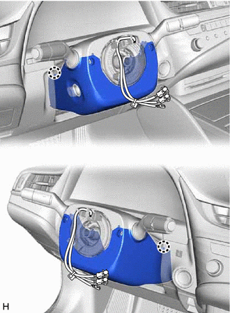
| (b) Install the 3 screws. |
|
.png)
12. ALIGN FRONT WHEELS FACING STRAIGHT AHEAD
13. INSPECT AND ADJUST SPIRAL CABLE WITH SENSOR SUB-ASSEMBLY
Click here
14. INSTALL STEERING WHEEL ASSEMBLY
Click here
15. CHECK STEERING WHEEL CENTER POINT
16. INSTALL HORN BUTTON ASSEMBLY
Click here
17. CUSTOMIZE POWER TILT AND POWER TELESCOPIC STEERING COLUMN SYSTEM
(a) Set the auto tilt away function setting to the previous condition by changing the customize parameter.
for Gasoline Model: Click here
for HV Model: Click here
18. PERFORM INITIALIZATION AND CALIBRATION (for Gasoline Model)
for Parking Assist Monitor System Initialization: Click here
for Parking Assist Monitor System Calibration: Click here
for Panoramic View Monitor System Initialization: Click here
for Panoramic View Monitor System Calibration: Click here
for Parking Support Brake System Calibration: Click here
19. PERFORM INITIALIZATION AND CALIBRATION (for HV Model)
for Parking Assist Monitor System Initialization: Click here
for Parking Assist Monitor System Calibration: Click here
for Panoramic View Monitor System Initialization: Click here
for Panoramic View Monitor System Calibration: Click here
for Parking Support Brake System Calibration: Click here
20. PERFORM REGISTRATION (for Gasoline Model)
Click here
21. PERFORM REGISTRATION (for HV Model)
Click here
READ NEXT:
 Steering Heater Switch
ComponentsCOMPONENTS ILLUSTRATION *1 RADIO RECEIVER ASSEMBLY WITH SWITCH *2 STEERING HEATER SWITCH (REFRESHING SEAT SWITCH) *3 RADIO RECEIVER ASSEMBLY - - RemovalREMOVAL PROCE
Components
COMPONENTS ILLUSTRATION *1 STEERING PAD SWITCH ASSEMBLY - -
SEE MORE:
Head restraints
Head restraints are provided for all
seats.
WARNING
■Head restraint precautions
Observe the following precautions
regarding the head restraints. Failure to
do so may result in death or serious
injury.
Use the head restraints designed for
each respective seat.
Adjust the head restrai
Inspection
INSPECTION PROCEDURE 1. INSPECT TRANSMISSION OIL CLEANER MAGNET (a) Use the removed transmission oil cleaner magnets to collect any steel chips. Examine the chips and particles in the transaxle housing and on the transmission oil cleaner magnets to determine what type of wear might be found in th
