Lexus ES: Disassembly
Lexus ES (XZ10) Service Manual / Brake / Brake System (other) / Vacuum Pump (for Tmc Made 2gr-fks) / Disassembly
DISASSEMBLY
PROCEDURE
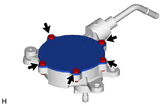
1. REMOVE END COVER
| (a) Using a T30 "TORX" socket wrench, remove the 5 screws and end cover. NOTICE:
|
|
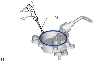
| (b) Using a screwdriver with its tip wrapped with protective tape, remove the No. 1 O-ring. NOTICE: Do not damage the groove. |
|
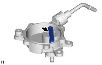
2. REMOVE VACUUM PUMP VANE
| (a) Remove the vacuum pump vane together with the 2 vacuum pump vane caps. NOTICE:
|
|
| (b) Remove the 2 vacuum pump vane caps from the vacuum pump vane. NOTICE:
|
|
.png)
READ NEXT:
 Inspection
INSPECTION PROCEDURE 1. INSPECT VACUUM PUMP VANE (a) Check that the vacuum pump vane or vacuum pump vane caps are not damaged or excessively worn. HINT: If the vacuum pump vane or vacuum pump vane
Installation
INSTALLATION PROCEDURE 1. INSTALL VACUUM PUMP ASSEMBLY (a) When using a new vacuum pump assembly: (1) Apply engine oil to the No. 2 O-ring and No. 3 O-ring which are installed to a new vacuum pump ass
On-vehicle Inspection
ON-VEHICLE INSPECTION PROCEDURE 1. REMOVE COWL TOP VENTILATOR LOUVER SUB-ASSEMBLY Click here 2. REMOVE FRONT CENTER UPPER SUSPENSION BRACE SUB-ASSEMBLY Click here 3. OPERATION CHECK (a) Slide the
SEE MORE:
Hydraulic Test
HYDRAULIC TEST PERFORM HYDRAULIC TEST CAUTION:
Do not perform a stall test if there are any people or objects near the vehicle.
The vehicle could begin moving suddenly, resulting in a serious accident.
Do not perform a stall test if any wheel chocks are out of position.
The vehicle co
Check Assist Limit Record
CAUTION / NOTICE / HINT HINT: Perform this troubleshooting procedure when no DTCs are output, including DTCs related to CAN communication system malfunctions. PROCEDURE 1. READ VALUE USING TECHSTREAM (ASSIST LIMIT RECORD 1) (a) Using the Techstream, read the Data List item "Assist Limit Rec
© 2016-2026 Copyright www.lexguide.net
