Lexus ES: Installation
INSTALLATION
PROCEDURE
1. INSTALL VACUUM PUMP ASSEMBLY
(a) When using a new vacuum pump assembly:
(1) Apply engine oil to the No. 2 O-ring and No. 3 O-ring which are installed to a new vacuum pump assembly.
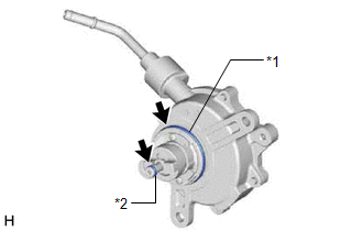
| *1 | No. 2 O-ring |
| *2 | No. 3 O-ring |
.png) | Engine oil |
(b) When reusing the vacuum pump assembly:
(1) Apply engine oil to a new No. 2 O-ring and No. 3 O-ring and install them to the vacuum pump assembly.
| *1 | No. 2 O-ring |
| *2 | No. 3 O-ring |
| | Engine oil |
(c) Apply engine oil to the inner surface of the installation hole.
| (d) Temporarily install the vacuum pump assembly so that the oil pipe engages with the hole of the camshaft and the coupling teeth engage with the groove of the camshaft. NOTICE:
|
|
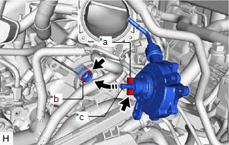
| (e) Install the vacuum pump assembly with the 3 bolts. Torque: 21 N·m {214 kgf·cm, 15 ft·lbf} NOTICE:
|
|
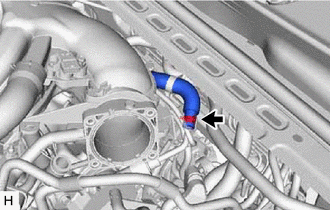
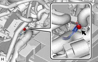
2. CONNECT AIR TUBE
| (a) Connect the air tube to the vacuum pump assembly and slide the clip to secure it. |
|
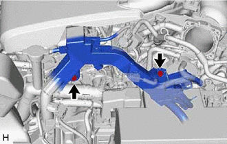
3. INSTALL ENGINE WIRE
| (a) Install the earth wire with the bolt. Torque: 10 N·m {102 kgf·cm, 7 ft·lbf} |
|
| (b) Install the engine wire with the 2 bolts. Torque: 10 N·m {102 kgf·cm, 7 ft·lbf} |
|
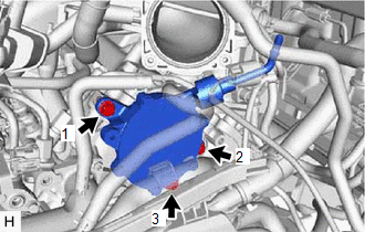
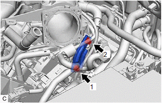
4. INSTALL NO. 2 SURGE TANK STAY
| (a) Install the No. 2 surge tank stay with the 2 bolts in the order shown in the illustration. Torque: 21 N·m {214 kgf·cm, 15 ft·lbf} |
|
5. INSTALL THROTTLE BODY WITH MOTOR ASSEMBLY
Click here .gif)
6. INSPECT VACUUM PUMP OPERATION
Click here
READ NEXT:
 On-vehicle Inspection
ON-VEHICLE INSPECTION PROCEDURE 1. REMOVE COWL TOP VENTILATOR LOUVER SUB-ASSEMBLY Click here 2. REMOVE FRONT CENTER UPPER SUSPENSION BRACE SUB-ASSEMBLY Click here 3. OPERATION CHECK (a) Slide the
Reassembly
REASSEMBLY PROCEDURE 1. INSTALL VACUUM PUMP VANE (a) Apply engine oil to the vacuum pump vane and vacuum pump vane caps and install the vacuum pump vane caps to the vacuum pump vane. (b) Apply engine
Removal
REMOVAL PROCEDURE 1. REMOVE THROTTLE BODY WITH MOTOR ASSEMBLY Click here 2. REMOVE NO. 2 SURGE TANK STAY Click here 3. SEPARATE ENGINE WIRE (a) Remove the 2 bolts and separate the engine wire.
SEE MORE:
Operation Check
OPERATION CHECK CHECK WINDSHIELD DEICER SYSTEM (a) Turn the engine switch on (IG). (b) Check that the windshield deicer wire (windshield glass) becomes warm by operating the front wiper deicer switch. (c) Confirm that windshield deicer system operation stops after approximately 15 minutes. NOTICE: I
Freeze Frame Data
FREEZE FRAME DATA FREEZE FRAME DATA NOTICE:
It is difficult to show the specified values (judgment values) clearly because freeze frame data values change significantly due to differences in measurement conditions, surroundings, or vehicle conditions. For this reason, there may be a problem even
