Lexus ES: Inspection
INSPECTION
PROCEDURE
1. INSPECT VACUUM PUMP VANE
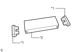
| (a) Check that the vacuum pump vane or vacuum pump vane caps are not damaged or excessively worn. HINT: If the vacuum pump vane or vacuum pump vane caps are damaged or excessively worn, replace the damaged parts with new ones. |
|
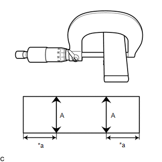
| (b) Using a micrometer, measure length (A) of the vacuum pump vane with the vacuum pump vane caps removed. Minimum Length (A): 23.8 mm (0.937 in.) NOTICE: Measure the length 10 mm (0.394 in.) in from each end of the vacuum pump vane. HINT: If the length is not as specified, replace the vacuum pump vane and vacuum pump vane caps with new ones. |
|
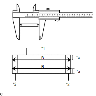
| (c) Using a vernier caliper, measure length (B) of the vacuum pump vane with the vacuum pump vane caps installed. Minimum Length (B): 80.5 mm (3.17 in.) NOTICE: Measure the length 5 mm (0.197 in.) in from each end of the vacuum pump vane caps. HINT: If the length is not as specified, replace the vacuum pump vane and vacuum pump vane caps with new ones. |
|
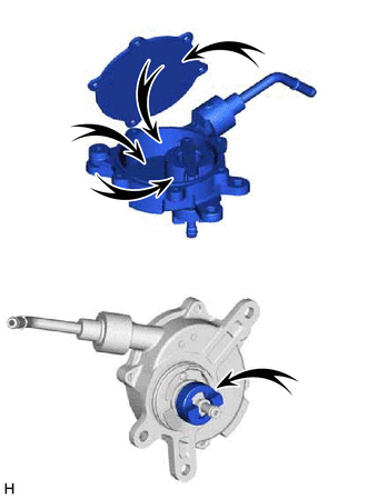
2. INSPECT VACUUM PUMP HOUSING
| (a) Check that the areas shown in the illustration are not damaged or excessively worn. HINT: If the areas shown in the illustration are damaged or excessively worn, replace the vacuum pump assembly. |
|
READ NEXT:
 Installation
INSTALLATION PROCEDURE 1. INSTALL VACUUM PUMP ASSEMBLY (a) When using a new vacuum pump assembly: (1) Apply engine oil to the No. 2 O-ring and No. 3 O-ring which are installed to a new vacuum pump ass
On-vehicle Inspection
ON-VEHICLE INSPECTION PROCEDURE 1. REMOVE COWL TOP VENTILATOR LOUVER SUB-ASSEMBLY Click here 2. REMOVE FRONT CENTER UPPER SUSPENSION BRACE SUB-ASSEMBLY Click here 3. OPERATION CHECK (a) Slide the
Reassembly
REASSEMBLY PROCEDURE 1. INSTALL VACUUM PUMP VANE (a) Apply engine oil to the vacuum pump vane and vacuum pump vane caps and install the vacuum pump vane caps to the vacuum pump vane. (b) Apply engine
SEE MORE:
Dtc Check / Clear
DTC CHECK / CLEAR CHECK DTC (a) Connect the Techstream to the DLC3. (b) Turn the engine switch on (IG). (c) Turn the Techstream on. (d) Enter the following menus: Body Electrical / Sliding Roof / Trouble Codes. Body Electrical > Sliding Roof > Trouble Codes (e) Check the details of the DTC(s).
Problem Symptoms Table
PROBLEM SYMPTOMS TABLE NOTICE:
The following inspection procedure of the panoramic view monitor system is described on the assumption that the audio and visual system*1 or navigation system*2 is normal. If the audio and visual system*1 or navigation system*2 has any malfunction, first proceed wit
