Lexus ES: Components
Lexus ES (XZ10) Service Manual / Audio & Visual & Telematics / Audio / Video / Noise Filter / Components
COMPONENTS
ILLUSTRATION
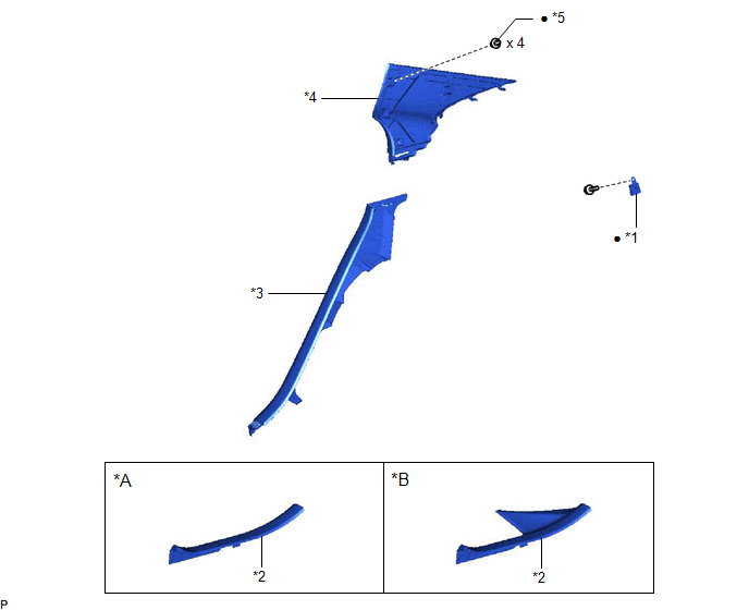
| *A | for HV Model | *B | for Gasoline Model |
| *1 | RADIO SETTING CONDENSER | *2 | REAR DOOR SCUFF PLATE LH |
| *3 | REAR SEAT SIDE GARNISH LH | *4 | ROOF SIDE INNER GARNISH ASSEMBLY LH |
| *5 | CLIP | - | - |
| ● | Non-reusable part | - | - |
READ NEXT:
 Installation
INSTALLATION PROCEDURE 1. INSTALL RADIO SETTING CONDENSER (a) Engage the claw to install a new terminal cover to the wire harness. NOTICE:
Make sure to hold the crimped side of the terminal wh
On-vehicle Inspection
ON-VEHICLE INSPECTION PROCEDURE 1. INSPECT RADIO SETTING CONDENSER (a) With the radio setting condenser installed, check that there is no looseness or other abnormalities. (b) Measure the resistanc
Removal
REMOVAL CAUTION / NOTICE / HINT The necessary procedures (adjustment, calibration, initialization, or registration) that must be performed after parts are removed and installed, or replaced during rad
SEE MORE:
Removal
REMOVAL PROCEDURE 1. REMOVE LUGGAGE LOCK CONTROL CABLE PLATE Click here 2. REMOVE SWITCH BEZEL (w/ Power Trunk Lid System) Click here 3. REMOVE LUGGAGE COMPARTMENT DOOR COVER Click here 4. REMOVE REAR SPOILER SUB-ASSEMBLY (a) Apply protective tape around the rear spoiler sub-assembly as shown
Data List / Active Test
DATA LIST / ACTIVE TEST ACTIVE TEST HINT: Using the Techstream to perform Active Tests allows relays, VSVs, actuators and other items to be operated without removing any parts. This non-intrusive functional inspection can be very useful because intermittent operation may be discovered before parts o
© 2016-2026 Copyright www.lexguide.net
