Lexus ES: Removal
REMOVAL
CAUTION / NOTICE / HINT
The necessary procedures (adjustment, calibration, initialization, or registration) that must be performed after parts are removed and installed, or replaced during radio setting condenser removal/installation are shown below.
Necessary Procedure After Parts Removed/Installed/Replaced (for HV Model)| Replaced Part or Performed Procedure | Necessary Procedures | Effect/Inoperative Function When Necessary Procedures are not Performed | Link |
|---|---|---|---|
|
*: When performing learning using the Techstream.
Click here | |||
| Disconnect cable from negative auxiliary battery terminal | Perform steering sensor zero point calibration | Lane Control System | |
| Pre-collision System | |||
| Parking Support Brake System* | |||
| Lighting System | |||
| Memorize steering angle neutral point | Parking Assist Monitor System | | |
| Panoramic View Monitor System | | ||
| Initialize power trunk lid system | Power Trunk Lid System | | |
CAUTION:
Some of these service operations affect the SRS airbag system. Read the precautionary notices concerning the SRS airbag system before servicing.
.png)
Click here .gif)
NOTICE:
- After the power switch is turned off, the radio receiver assembly records various types of memory and settings. As a result, after turning the power switch off, make sure to wait at least 85 seconds before disconnecting the cable from the negative (-) auxiliary battery terminal. (for Audio and Visual System)
- After the power switch is turned off, the radio receiver assembly records various types of memory and settings. As a result, after turning the power switch off, make sure to wait at least 85 seconds before disconnecting the cable from the negative (-) auxiliary battery terminal. (for Navigation System)
| Replaced Part or Performed Procedure | Necessary Procedures | Effect/Inoperative Function When Necessary Procedures are not Performed | Link |
|---|---|---|---|
|
*: When performing learning using the Techstream.
Click here | |||
| Disconnect cable from negative battery terminal | Perform steering sensor zero point calibration | Lane Control System | |
| Pre-collision System | |||
| Parking Support Brake System* | |||
| Lighting System | |||
| Memorize steering angle neutral point | Parking Assist Monitor System | | |
| Panoramic View Monitor System | | ||
| Initialize power trunk lid system | Power Trunk Lid System | | |
CAUTION:
Some of these service operations affect the SRS airbag system. Read the precautionary notices concerning the SRS airbag system before servicing.
Click here
NOTICE:
- After the engine switch is turned off, the radio receiver assembly records various types of memory and settings. As a result, after turning the engine switch off, make sure to wait at least 85 seconds before disconnecting the cable from the negative (-) battery terminal. (for Audio and Visual System)
- After the engine switch is turned off, the radio receiver assembly records various types of memory and settings. As a result, after turning the engine switch off, make sure to wait at least 85 seconds before disconnecting the cable from the negative (-) battery terminal. (for Navigation System)
PROCEDURE
1. REMOVE REAR SEAT ASSEMBLY
Click here
2. REMOVE REAR DOOR SCUFF PLATE LH
for HV Model: Click here
for Gasoline Model: Click here
3. REMOVE REAR SEAT SIDE GARNISH LH
Click here
4. REMOVE ROOF SIDE INNER GARNISH ASSEMBLY LH
Click here
5. REMOVE RADIO SETTING CONDENSER
NOTICE:
When the terminal cover is removed, the radio setting condenser must be replaced because the terminal cover and condenser are supplied as a set.
| (a) Remove the bolt. |
|
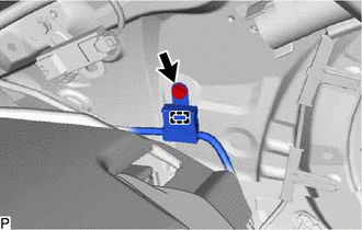
(b) Disengage the clamp and disconnect the radio setting condenser with wire harness from the vehicle body.
(c) Using a screwdriver, disengage the 3 claws and remove the terminal cover with wire harness from the condenser as shown in the illustration.
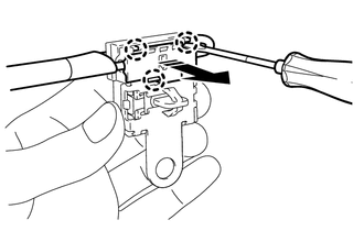
.png) | Remove in this Direction |
| (d) Using a screwdriver, bend back and break off the claw as shown in the illustration. |
|
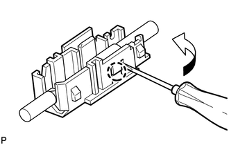
(e) Remove the terminal cover from the wire harness.
NOTICE:
- Make sure to hold the crimped side of the terminal when disconnecting the wire harness from the terminal cover.
- Make sure not to bend the exposed wire when disconnecting the wire harness from the terminal cover.
- Check for deformation of the terminal after the wire harness has been removed from the terminal cover.
READ NEXT:
 Components
COMPONENTS ILLUSTRATION *A w/o Manual (SOS) Switch *B w/ Manual (SOS) Switch *1 ANTENNA CORD SUB-ASSEMBLY *2 NO. 2 SIDE DEFROSTER NOZZLE DUCT *3 NO. 3 HEATER TO REGISTER DUCT
Installation
INSTALLATION PROCEDURE 1. INSTALL NO. 3 ANTENNA CORD SUB-ASSEMBLY (w/ Manual (SOS) Switch) (a) Engage the 5 clamps to install the No. 3 antenna cord sub-assembly. (b) Connect the connector. 2. INSTALL
SEE MORE:
Transmitter ID1 Operation Stop (C2111-C2114)
DESCRIPTION The tire pressure warning valve and transmitters that are installed in the tire and wheel assemblies measure the tire pressure of each wheel. The measured values are transmitted to the tire pressure warning ECU and receiver in the vehicle as radio waves. The ECU compares the measured tir
Abnormal Height Sensor Data at Initialization (B2452)
DESCRIPTION The headlight ECU sub-assembly LH stores this DTC if the value from the rear height control sensor sub-assembly LH is out of range when performing initialization of the headlight ECU sub-assembly LH, such as when the vehicle is not level or jacked up. DTC No. Detection Item DTC De
