Lexus ES: Installation
INSTALLATION
PROCEDURE
1. INSTALL SPEAKER ASSEMBLY WITH BRACKET
NOTICE:
Do not touch the speaker cone.
| (a) Install the speaker assembly with bracket with the 4 bolts. Torque: 8.0 N·m {82 kgf·cm, 71 in·lbf} HINT: Install the bolts in the order shown in the illustration. |
|
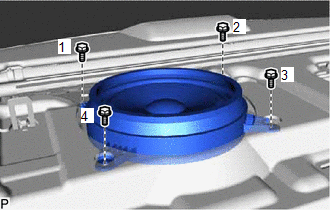
(b) Connect the connector.
2. INSTALL PACKAGE TRAY TRIM PANEL ASSEMBLY (w/o Rear Sunshade)
Click here .gif)
3. INSTALL PACKAGE TRAY TRIM PANEL ASSEMBLY (w/ Rear Sunshade)
Click here
4. INSTALL REAR SEAT SHOULDER BELT COVER
Click here
5. INSTALL CENTER STOP LIGHT SET (w/o Rear Sunshade)
Click here
6. CONNECT REAR SEAT OUTER BELT ASSEMBLY LH
Click here
7. CONNECT REAR SEAT OUTER BELT ASSEMBLY RH
HINT:
Use the same procedure as for the LH side.
8. INSTALL ROOF SIDE INNER GARNISH ASSEMBLY LH
Click here
9. INSTALL ROOF SIDE INNER GARNISH ASSEMBLY RH
HINT:
Use the same procedure as for the LH side.
10. INSTALL REAR SEAT SIDE GARNISH LH
Click here
11. INSTALL REAR SEAT SIDE GARNISH RH
HINT:
Use the same procedure as for the LH side.
12. INSTALL REAR DOOR SCUFF PLATE LH (for HV Model)
Click here
13. INSTALL REAR DOOR SCUFF PLATE LH (for Gasoline Model)
Click here
14. INSTALL REAR DOOR SCUFF PLATE RH (for HV Model)
HINT:
Use the same procedure as for the LH side.
15. INSTALL REAR DOOR SCUFF PLATE RH (for Gasoline Model)
HINT:
Use the same procedure as for the LH side.
16. INSTALL REAR SEAT ASSEMBLY
Click here
READ NEXT:
 Removal
REMOVAL CAUTION / NOTICE / HINT The necessary procedures (adjustment, calibration, initialization, or registration) that must be performed after parts are removed and installed, or replaced during spe
Components
COMPONENTS ILLUSTRATION *A for Moon Roof - - *1 TELEPHONE ANTENNA ASSEMBLY *2 TELEPHONE ANTENNA ASSEMBLY WITH COVER *3 COVER *4 WASHER AND HOLDER *5 SEAL *6 TEL
SEE MORE:
Data List / Active Test
DATA LIST / ACTIVE TEST DATA LIST HINT: Using the Techstream to read the Data List allows the values or states of switches, sensors, actuators and other items to be read without removing any parts. This non-intrusive inspection can be very useful because intermittent conditions or signals may be dis
Disposal
DISPOSAL PROCEDURE 1. DISPOSE OF REAR SHOCK ABSORBER ASSEMBLY CAUTION:
Always use a cloth to prevent shards of metal from flying about due to the release of pressurized gas.
Always wear safety glasses.
HINT: The gas is colorless, odorless and non-poisonous. (a) Extend the piston rod and
