Lexus ES: On-vehicle Inspection
ON-VEHICLE INSPECTION
PROCEDURE
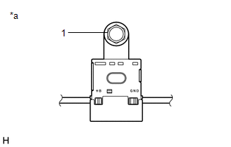
1. INSPECT RADIO SETTING CONDENSER
(a) With the radio setting condenser installed, check that there is no looseness or other abnormalities.
| (b) Measure the resistance of the radio setting condenser according to the value(s) in the table below. Standard Resistance:
|
| |||||||||||||
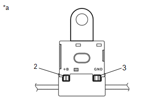
(c) Remove the bolt.
(d) Disengage the clamp and disconnect the radio setting condenser with wire harness from the vehicle body.
| (e) Measure the resistance and voltage of the radio setting condenser according to the value(s) in the table below. Standard Resistance:
Standard Voltage:
|
| |||||||||||||||||||||||||
READ NEXT:
 Removal
REMOVAL CAUTION / NOTICE / HINT The necessary procedures (adjustment, calibration, initialization, or registration) that must be performed after parts are removed and installed, or replaced during rad
Components
COMPONENTS ILLUSTRATION *A w/o Manual (SOS) Switch *B w/ Manual (SOS) Switch *1 ANTENNA CORD SUB-ASSEMBLY *2 NO. 2 SIDE DEFROSTER NOZZLE DUCT *3 NO. 3 HEATER TO REGISTER DUCT
SEE MORE:
Replacement
REPLACEMENT CAUTION / NOTICE / HINT The necessary procedures (adjustment, calibration, initialization, or registration) that must be performed after parts are removed and installed, or replaced during diaphragm oil seal removal/installation are shown below. Necessary Procedures After Parts Removed/I
Disassembly
DISASSEMBLY CAUTION / NOTICE / HINT HINT:
Use the same procedure for the RH side and LH side.
The following procedure is for the LH side.
PROCEDURE 1. REMOVE HEADLIGHT ECU SUB-ASSEMBLY Click here 2. REMOVE HEADLIGHT GASKET Click here 3. REMOVE HEADLIGHT RIM (for TMC Made) Click here 4.
