Lexus ES: Components
COMPONENTS
ILLUSTRATION
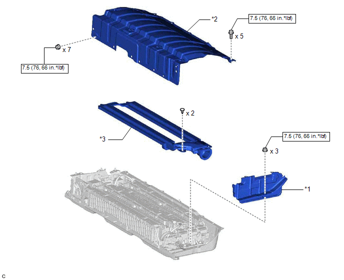
| *1 | BATTERY ECU ASSEMBLY | *2 | UPPER HV BATTERY COVER SUB-ASSEMBLY |
| *3 | NO. 1 HV BATTERY HOSE | - | - |
.png) | N*m (kgf*cm, ft.*lbf): Specified torque | - | - |
ILLUSTRATION
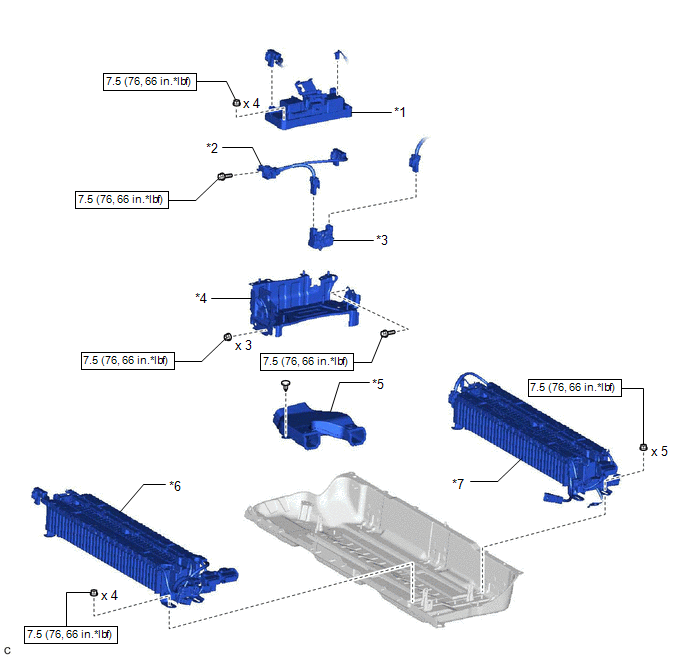
| *1 | HV BATTERY JUNCTION BLOCK ASSEMBLY | *2 | ELECTRIC VEHICLE BATTERY PLUG ASSEMBLY |
| *3 | HYBRID BATTERY TERMINAL BLOCK | *4 | NO. 2 HYBRID BATTERY SHIELD SUB-ASSEMBLY |
| *5 | NO. 1 HV BATTERY INTAKE DUCT LH | *6 | NO. 1 HV SUPPLY STACK SUB-ASSEMBLY |
| *7 | NO. 2 HV SUPPLY STACK SUB-ASSEMBLY | - | - |
| | N*m (kgf*cm, ft.*lbf): Specified torque | - | - |
READ NEXT:
 Basic Inspection
DESCRIPTION When replacing the No. 1 HV supply stack sub-assembly or No. 2 HV supply stack sub-assembly, it is necessary to check, adjust and equalize the SOC of the HV battery. Otherwise, the engine
Inspection
INSPECTION PROCEDURE 1. INSPECT HV SUPPLY STACK SUB-ASSEMBLY CAUTION: Be sure to wear insulated gloves and protective goggles. (a) Remove the HV supply stack sub-assembly. Click here (b) Inspect th
Installation
INSTALLATION PROCEDURE 1. INSTALL NO. 2 HV SUPPLY STACK SUB-ASSEMBLY CAUTION: Be sure to wear insulated gloves and protective goggles. (a) Install the No. 2 HV supply stack sub-assembly with the 4 nut
SEE MORE:
System Diagram
SYSTEM DIAGRAM HEADLIGHT ASSEMBLY CIRCUIT (for LED Type Turn Signal Light) HEADLIGHT ASSEMBLY CIRCUIT (for Bulb Type Turn Signal Light) (for TMC Made) HEADLIGHT ASSEMBLY CIRCUIT (for Bulb Type Turn Signal Light) (for TMMK Made)
Removal
REMOVAL CAUTION / NOTICE / HINT HINT:
Use the same procedure for the RH side and LH side.
The following procedure is for the LH side.
PROCEDURE 1. REMOVE HOOD SUPPORT ASSEMBLY NOTICE:
Avoid touching the piston rod as much as possible to prevent foreign matter from attaching to it. Be sure
© 2016-2026 Copyright www.lexguide.net
