Lexus ES: Installation
INSTALLATION
PROCEDURE
1. INSTALL PARK/NEUTRAL POSITION SWITCH ASSEMBLY
(a) Temporarily install the park/neutral position switch assembly to the automatic transaxle case sub-assembly with the 2 bolts.
NOTICE:
Before installing the park/neutral position switch assembly, remove any dirt or rust on the manual valve lever shaft sub-assembly. Be sure to install the park/neutral position switch assembly straight along the manual valve lever shaft sub-assembly while being careful not to deform the plate spring that supports the manual valve lever shaft sub-assembly. If the plate spring is deformed, the park/neutral position switch assembly cannot be installed correctly.
(b) Temporarily install the transmission control shaft lever to the park/neutral position switch assembly.
| (c) Turn the transmission control shaft lever clockwise until it stops, then turn it counterclockwise 2 notches. |
|
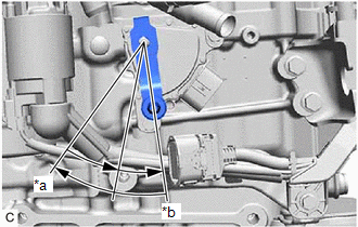
(d) Remove the transmission control shaft lever from the park/neutral position switch assembly.
| (e) Align the protrusion with the neutral basic line. |
|
.png)
(f) Hold the park/neutral position switch assembly in that position and tighten the 2 bolts.
Torque:
5.4 N·m {55 kgf·cm, 48 in·lbf}
(g) Install the transmission control shaft lever to the manual valve lever shaft sub-assembly with the washer and nut.
Torque:
12.7 N·m {130 kgf·cm, 9 ft·lbf}
(h) Connect the park/neutral position switch assembly connector.
2. CONNECT TRANSMISSION CONTROL CABLE ASSEMBLY
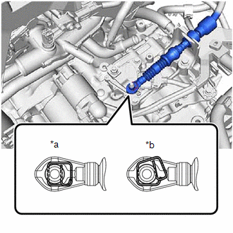
| (a) Connect the transmission control cable assembly to the transmission control shaft lever as shown in the illustration. NOTICE: Before connecting the transmission control cable assembly, check that the park/neutral position switch assembly and shift lever are in N. |
|
3. INSTALL BATTERY CLAMP SUB-ASSEMBLY
Click here .gif)
4. INSTALL ECM
Click here
5. INSTALL BATTERY
Click here
6. INSPECT PARK/NEUTRAL POSITION SWITCH ASSEMBLY OPERATION
Click here
7. INSPECT SHIFT LEVER POSITION
Click here
8. ADJUST SHIFT LEVER POSITION
Click here
READ NEXT:
 On-vehicle Inspection
ON-VEHICLE INSPECTION PROCEDURE 1. SECURE VEHICLE (a) Fully apply the parking brake and chock a wheel. CAUTION:
Make sure to apply the parking brake and chock a wheel before performing this procedu
Removal
REMOVAL CAUTION / NOTICE / HINT The necessary procedures (adjustment, calibration, initialization or registration) that must be performed after parts are removed and installed, or replaced during park
Shift Lever Knob
ComponentsCOMPONENTS ILLUSTRATION *1 SHIFT LEVER KNOB SUB-ASSEMBLY - - InstallationINSTALLATION PROCEDURE 1. INSTALL SHIFT LEVER KNOB SUB-ASSEMBLY (a) Install the shift lever knob su
SEE MORE:
Freeze Frame Data
FREEZE FRAME DATA FREEZE FRAME DATA (a) Whenever a DTC is detected, the windshield wiper motor assembly stores the current vehicle state as Freeze Frame Data. CHECK FREEZE FRAME DATA (a) Connect the Techstream to the DLC3. (b) Turn the power switch on (IG). (c) Turn the Techstream on. (d) Enter the
Poor Sound Quality in All Modes (Low Volume)
PROCEDURE 1. CHECK AUDIO SETTINGS (a) Set treble, middle and bass to the initial values and check that the sound is normal. OK: The sound returns to normal. HINT: Sound quality adjustment measures vary according to the type of amplifier. OK END
NG 2. COMPARE
