
Lexus ES: Components
Lexus ES (XZ10) Service Manual / Engine & Hybrid System / Hybrid / Battery Control / Fuse Box / Components
COMPONENTS
ILLUSTRATION
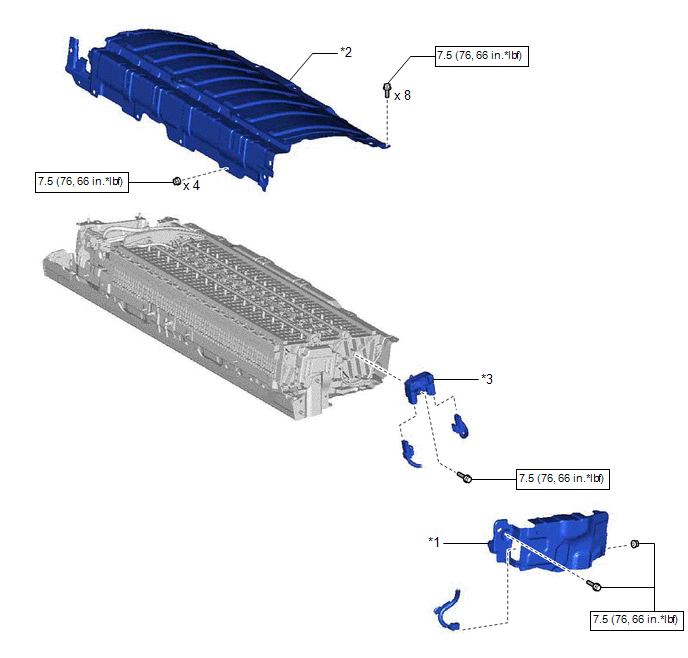
| *1 | NO. 1 HV BATTERY SHIELD PANEL | *2 | UPPER HV BATTERY COVER SUB-ASSEMBLY |
| *3 | HYBRID BATTERY TERMINAL BLOCK | - | - |
.png) | N*m (kgf*cm, ft.*lbf): Specified torque | - | - |
READ NEXT:
 Removal
REMOVAL CAUTION / NOTICE / HINT The necessary procedures (adjustment, calibration, initialization or registration) that must be performed after parts are removed and installed, or replaced during hybr
Inspection
INSPECTION PROCEDURE 1. INSPECT HYBRID BATTERY TERMINAL BLOCK (a) Measure the resistance according to the value(s) in the table below. Standard Resistance: Tester Connection Condition Speci
Installation
INSTALLATION PROCEDURE 1. INSTALL HYBRID BATTERY TERMINAL BLOCK CAUTION: Be sure to wear insulated gloves and protective goggles. (a) Connect the 2 hybrid battery terminal block connectors. NOTICE: Ma
SEE MORE:
Automatic High Beam System (B124B)
DESCRIPTION The main body ECU (multiplex network body ECU) determines the status of the automatic high beam system based on the automatic high beam system signal from the forward recognition camera. DTC No. Detection Item DTC Detection Condition Trouble Area DTC Output from B124B Au
Motor Electronics Coolant Temperature Sensor Circuit Short to Ground (P0A0011,P0A0015)
DESCRIPTION Refer to the description for DTC P0A001C. Click here DTC No. Detection Item DTC Detection Condition Trouble Area MIL Warning Indicate P0A0011 Motor Electronics Coolant Temperature Sensor Circuit Short to Ground Short to ground detected in HV coolant temperature sen
© 2016-2026 Copyright www.lexguide.net
