Lexus ES: Components
COMPONENTS
ILLUSTRATION
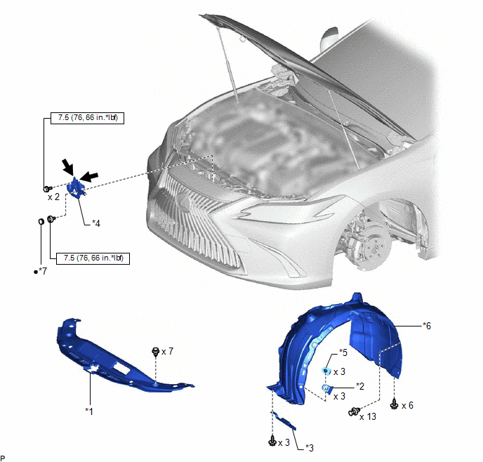
| *1 | COOL AIR INTAKE DUCT SEAL | *2 | FRONT FENDER LINER RETAINER |
| *3 | FRONT WHEEL OPENING EXTENSION PAD LH | *4 | HOOD LOCK ASSEMBLY |
| *5 | PIN HOLD CLIP | *6 | REAR FENDER SPLASH SHIELD SUB-ASSEMBLY LH |
| *7 | HOOD LOCK NUT CAP | - | - |
.png) | N*m (kgf*cm, ft.*lbf): Specified torque | ● | Non-reusable part |
.png) | MP grease | - | - |
ILLUSTRATION
.png)
| *1 | COWL SIDE TRIM BOARD LH | *2 | FRONT DOOR OPENING TRIM COVER LH |
| *3 | FRONT DOOR SCUFF PLATE LH | *4 | HOOD LOCK CONTROL CABLE ASSEMBLY |
| *5 | HOOD LOCK CONTROL LEVER SUB-ASSEMBLY | *6 | INSTRUMENT SIDE PANEL LH |
| *7 | LOWER INSTRUMENT PANEL FINISH PANEL SUB-ASSEMBLY | *8 | NO. 1 INSTRUMENT PANEL UNDER COVER SUB-ASSEMBLY |
READ NEXT:
 Removal
REMOVAL PROCEDURE 1. REMOVE FRONT WHEEL LH Click here 2. REMOVE FRONT WHEEL OPENING EXTENSION PAD LH HINT: Use the same procedure as for the RH side. Click here 3. REMOVE REAR FENDER SPLASH SHIELD
Removal
REMOVAL PROCEDURE 1. REMOVE FRONT WHEEL LH Click here 2. REMOVE FRONT WHEEL OPENING EXTENSION PAD LH HINT: Use the same procedure as for the RH side. Click here 3. REMOVE REAR FENDER SPLASH SHIELD
Installation
INSTALLATION PROCEDURE 1. INSTALL HOOD LOCK CONTROL CABLE ASSEMBLY (a) Pass the hood lock control cable assembly into the engine compartment. (b) Engage the grommet. (c) Engage each clamp. (d) Engage
SEE MORE:
Vehicle Approaching Sound ECU Communication Stop Mode
DESCRIPTION Detection Item Symptom Trouble Area Vehicle Approaching Sound ECU Communication Stop Mode Any of the following conditions are met:
Communication stop for "Vehicle Proximity Notification System" is indicated on the "Communication Bus Check" screen of the Techstream.
Click
Removal
REMOVAL PROCEDURE 1. REMOVE INSTRUMENT CLUSTER FINISH PANEL ASSEMBLY Click here 2. REMOVE DRIVE MODE SELECT SWITCH (COMBINATION SWITCH ASSEMBLY) (a) Disconnect the drive mode select switch (combination switch assembly) connector. (b) Disengage the clamp to disconnect the wire harne
© 2016-2026 Copyright www.lexguide.net
