Lexus ES: Components
Lexus ES (XZ10) Service Manual / Engine & Hybrid System / A25a-fxs (emission Control) / Egr Valve / Components
COMPONENTS
ILLUSTRATION
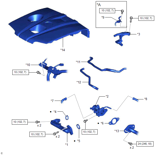
| *A | for EGR Valve Bracket Connection Type | - | - |
| *1 | NO. 1 EGR PIPE SUB-ASSEMBLY | *2 | EGR VALVE ASSEMBLY |
| *3 | EGR VALVE BRACKET | *4 | EGR INLET GASKET |
| *5 | EGR VALVE ADAPTER GASKET | *6 | EGR VALVE GASKET |
| *7 | NO. 8 WATER BY-PASS HOSE | *8 | NO. 4 WATER BY-PASS HOSE |
| *9 | FUEL PIPE SUB-ASSEMBLY | *10 | ENGINE WIRE |
| *11 | NO. 1 FUEL VAPOR FEED HOSE | *12 | NO. 2 FUEL VAPOR FEED HOSE |
| *13 | EGR COOLER ASSEMBLY | *14 | NO. 1 ENGINE COVER SUB-ASSEMBLY |
.png) | N*m (kgf*cm, ft.*lbf): Specified torque | ● | Non-reusable part |
READ NEXT:
 Removal
REMOVAL CAUTION / NOTICE / HINT The necessary procedures (adjustment, calibration, initialization or registration) that must be performed after parts are removed and installed, or replaced during EGR
Inspection
INSPECTION PROCEDURE 1. INSPECT EGR VALVE ASSEMBLY (a) Measure the resistance according to the value(s) in the table below. Standard Resistance: Tester Connection Condition Specified Condit
Installation
INSTALLATION CAUTION / NOTICE / HINT NOTICE: This procedure includes the installation of small-head bolts. Refer to Small-Head Bolts of Basic Repair Hint to identify the small-head bolts. Click here
SEE MORE:
Removal
REMOVAL CAUTION / NOTICE / HINT The necessary procedures (adjustment, calibration, initialization or registration) that must be performed after parts are removed and installed, or replaced during fuel pump assembly removal/installation are shown below. Necessary Procedures After Parts Removed/Instal
Speed Signal Malfunction (B15C2)
DESCRIPTION The navigation ECU receives a vehicle speed signal from the combination meter assembly and information from the navigation antenna assembly, and then adjusts the vehicle position on the map. The navigation ECU stores this DTC when the difference between the speed information that the nav
© 2016-2026 Copyright www.lexguide.net
