Lexus ES: Removal
REMOVAL
CAUTION / NOTICE / HINT
The necessary procedures (adjustment, calibration, initialization or registration) that must be performed after parts are removed and installed, or replaced during EGR valve assembly removal/installation are shown below.
Necessary Procedures After Parts Removed/Installed/Replaced| Replaced Part or Performed Procedure | Necessary Procedure | Effect/Inoperative Function when Necessary Procedure not Performed | Link |
|---|---|---|---|
| Inspection After Repair |
| |
NOTICE:
This procedure includes the removal of small-head bolts. Refer to Small-Head Bolts of Basic Repair Hint to identify the small-head bolts.
Click here .gif)
PROCEDURE
1. DRAIN ENGINE COOLANT (for Engine)
Click here
2. REMOVE NO. 1 ENGINE COVER SUB-ASSEMBLY
Click here
3. DISCONNECT ENGINE WIRE
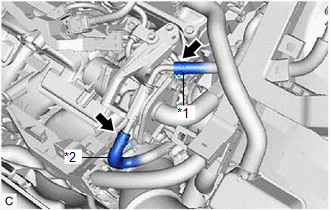
| (a) Disengage the 3 hose clamps and disconnect the No. 1 fuel vapor feed hose and No. 2 fuel vapor feed hose. |
|
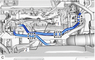
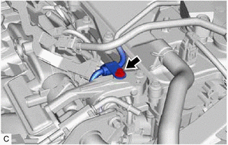
| (b) Disconnect the EGR valve assembly connector. |
|
(c) Remove the bolt.
(d) Disengage the 2 wire harness clamps and disconnect the engine wire.
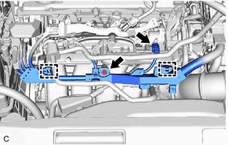
4. DISCONNECT EGR COOLER ASSEMBLY
| (a) Remove the 2 bolts and disconnect the EGR cooler assembly from the EGR valve assembly. |
|
(b) Remove the EGR valve gasket from the EGR valve assembly.
5. REMOVE NO. 1 EGR PIPE SUB-ASSEMBLY
| (a) Using an 8 mm socket wrench, remove the 4 bolts and No. 1 EGR pipe sub-assembly from the intake manifold and EGR valve assembly. |
|
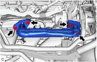
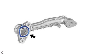
| (b) Remove the EGR valve adapter gasket from the No. 1 EGR pipe sub-assembly. |
|
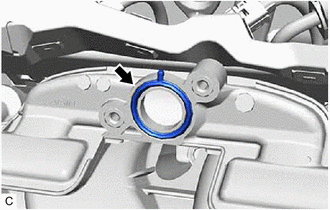
| (c) Remove the EGR inlet gasket from the intake manifold. |
|
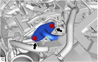
6. REMOVE EGR VALVE ASSEMBLY
| (a) Slide the 2 clips and disconnect the No. 4 water by-pass hose and No. 8 water by-pass hose from the EGR valve assembly. |
|
| (b) for EGR Valve Bracket Connection Type: (1) Using an 8 mm socket wrench, remove the bolt and disconnect the fuel pipe sub-assembly from the EGR valve bracket. |
|
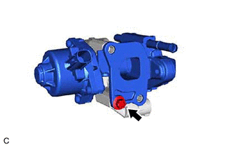
| (c) Using the 8 mm socket wrench, remove the bolt. |
|

| (d) Remove the EGR valve assembly with the EGR valve bracket from the camshaft housing vertically. |
|
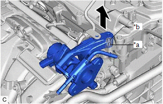
| (e) Using the 8 mm socket wrench, remove the bolt and EGR valve assembly from the EGR valve bracket. |
|
READ NEXT:
 Inspection
INSPECTION PROCEDURE 1. INSPECT EGR VALVE ASSEMBLY (a) Measure the resistance according to the value(s) in the table below. Standard Resistance: Tester Connection Condition Specified Condit
Installation
INSTALLATION CAUTION / NOTICE / HINT NOTICE: This procedure includes the installation of small-head bolts. Refer to Small-Head Bolts of Basic Repair Hint to identify the small-head bolts. Click here
SEE MORE:
Hybrid/EV Battery Current Sensor "A" Circuit Range/Performance (P0ABF00)
DESCRIPTION A battery current sensor is installed to the positive (+) terminal side of the HV battery and detects current flowing from the HV battery. The battery current sensor outputs voltage, which changes between 0 and 5 V according to the detected amperage, to the IB terminal of the battery vol
Red Indicator Remains On
DESCRIPTION This means that the DCM (telematics transceiver) has detected a malfunction in the safety connect system and stored a DTC or specific vehicle control history (RoB) Code. PROCEDURE 1. CHECK DTC (a) Turn the power switch off. (b) Connect the Techstream to the DLC3. (c) Turn the po
