Lexus ES: Installation
INSTALLATION
CAUTION / NOTICE / HINT
NOTICE:
This procedure includes the installation of small-head bolts. Refer to Small-Head Bolts of Basic Repair Hint to identify the small-head bolts.
Click here .gif)
PROCEDURE
1. INSTALL EGR VALVE ASSEMBLY
HINT:
Perform "Inspection After Repair" after replacing the EGR valve assembly.
Click here
(a) Using an 8 mm socket wrench, install the EGR valve assembly to the EGR valve bracket with the bolt.
Torque:
10 N·m {102 kgf·cm, 7 ft·lbf}
| (b) Align and fit the hole of the EGR valve bracket to the pin of the camshaft housing. |
|
(c) Using the 8 mm socket wrench, install the EGR valve assembly with the EGR valve bracket to the camshaft housing with the bolt.
Torque:
10 N·m {102 kgf·cm, 7 ft·lbf}
(d) for EGR Valve Bracket Connection Type:
(1) Using the 8 mm socket wrench, connect the fuel pipe sub-assembly to the EGR valve bracket with the bolt.
Torque:
10 N·m {102 kgf·cm, 7 ft·lbf}
(e) Connect the No. 4 water by-pass hose and No. 8 water by-pass hose to the EGR valve assembly and slide the 2 clips to secure them.
2. INSTALL NO. 1 EGR PIPE SUB-ASSEMBLY
(a) Install a new EGR inlet gasket to the intake manifold.
(b) Install a new EGR valve adapter gasket to the No. 1 EGR pipe sub-assembly.
(c) Using an 8 mm socket wrench, install the No. 1 EGR pipe sub-assembly to the intake manifold and EGR valve assembly with the 4 bolts.
Torque:
10 N·m {102 kgf·cm, 7 ft·lbf}
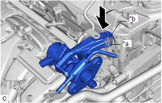
3. CONNECT EGR COOLER ASSEMBLY
| (a) Install a new EGR valve gasket to the EGR valve assembly. NOTICE: Make sure that the claws of the EGR valve gasket are toward the EGR valve assembly side. |
|
.png)
(b) Connect the EGR cooler assembly to the EGR valve assembly with the 2 bolts.
Torque:
24 N·m {245 kgf·cm, 18 ft·lbf}
4. CONNECT ENGINE WIRE
(a) Engage the 2 wire harness clamps to connect the engine wire.
(b) Install the bolt.
Torque:
10 N·m {102 kgf·cm, 7 ft·lbf}
(c) Connect the EGR valve assembly connector.
| (d) Engage the 3 hose clamps to connect the No. 1 fuel vapor feed hose and No. 2 fuel vapor feed hose. |
|
.png)
5. INSTALL NO. 1 ENGINE COVER SUB-ASSEMBLY
Click here
6. ADD ENGINE COOLANT (for Engine)
Click here
7. INSPECT FOR COOLANT LEAK (for Engine)
Click here
8. INSPECT FOR EXHAUST GAS LEAK
Click here
9. PERFORM INITIALIZATION
(a) Perform "Inspection After Repair" after replacing the EGR valve assembly.
Click here
READ NEXT:
 Parts Location
PARTS LOCATION ILLUSTRATION *1 CANISTER (CHARCOAL CANISTER ASSEMBLY) *2 EGR VALVE ASSEMBLY *3 FUEL TANK CAP ASSEMBLY *4 FUEL VAPOR CONTAINMENT VALVE (FUEL TANK SOLENOID MAIN VALVE
System Diagram
SYSTEM DIAGRAM *1 Intake Manifold *2 Purge Valve (Purge VSV) *3 Throttle Valve *4 Canister (Charcoal Canister Assembly) *5 Air Cleaner *6 ECM *7 Canister Filter *
SEE MORE:
Components
COMPONENTS ILLUSTRATION *A Type A *B Type B *1 FRONT FLOOR COVER RH - - N*m (kgf*cm, ft.*lbf): Specified torque - - ILLUSTRATION *A Type A *B Type B *1 FRONT FLOOR COVER LH - - N*m (kgf*cm, ft.*lbf): Specified torque - - ILLUSTRATIO
Hybrid/EV Battery Energy Control Module Unexpected Operation (P0A1F94)
DTC SUMMARY MALFUNCTION DESCRIPTION The hybrid vehicle control ECU (main CPU) monitors the battery ECU assembly. The cause of this malfunction may be the following: Battery ECU assembly internal malfunction
Battery ECU assembly malfunction
DESCRIPTION The hybrid vehicle control ECU (main CPU)
