Lexus ES: Removal
REMOVAL
CAUTION / NOTICE / HINT
The necessary procedures (adjustment, calibration, initialization or registration) that must be performed after parts are removed and installed, or replaced during fuel pump assembly removal/installation are shown below.
Necessary Procedures After Parts Removed/Installed/Replaced| Replaced Part or Performed Procedure | Necessary Procedure | Effect/Inoperative Function when Necessary Procedure not Performed | Link |
|---|---|---|---|
|
*: When performing learning using the Techstream.
Click here | |||
| Battery terminal is disconnected/reconnected | Perform steering sensor zero point calibration | Lane Control System (for Gasoline Model) | |
| Pre-collision System (for Gasoline Model) | |||
| Parking Support Brake System (for Gasoline Model)* | |||
| Lighting System (for Gasoline Model) | |||
| Memorize steering angle neutral point | Parking Assist Monitor System (for Gasoline Model) | | |
| Panoramic View Monitor System (for Gasoline Model) | | ||
| Initialize power trunk lid system | Power Trunk Lid System (for Gasoline Model) | | |
| Inspection after repair |
| |
CAUTION:
-
Never perform work on fuel system components near any possible ignition sources.
.png)
- Vaporized fuel could ignite, resulting in a serious accident.
-
Do not perform work on fuel system components without first disconnecting the cable from the negative (-) battery terminal.
.png)
- Sparks could cause vaporized fuel to ignite, resulting in a serious accident.
-
To prevent serious injury due to fuel spray from the high-pressure fuel lines, always discharge fuel system pressure before removing any fuel system components.
.png)
NOTICE:
- After the engine switch is turned off, the radio receiver assembly records various types of memory and settings. As a result, after turning the engine switch off, make sure to wait at least 85 seconds before disconnecting the cable from the negative (-) battery terminal. (for Audio and Visual System)
- After the engine switch is turned off, the radio receiver assembly records various types of memory and settings. As a result, after turning the engine switch off, make sure to wait at least 85 seconds before disconnecting the cable from the negative (-) battery terminal. (for Navigation System)
PROCEDURE
1. PRECAUTION
NOTICE:
After turning the engine switch off, waiting time may be required before disconnecting the cable from the negative (-) battery terminal. Therefore, make sure to read the disconnecting the cable from the negative (-) battery terminal notices before proceeding with work.
2. DISCHARGE FUEL SYSTEM PRESSURE
Click here .gif)
3. DISCONNECT CABLE FROM NEGATIVE BATTERY TERMINAL
Click here
4. REMOVE INTAKE MANIFOLD
Click here
5. REMOVE FUEL PUMP PROTECTOR
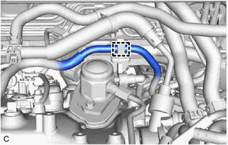
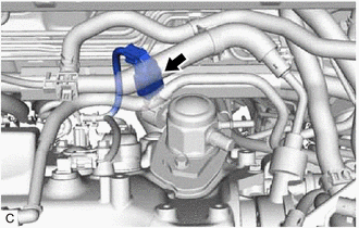
| (a) Disengage the clamp to disconnect the fuel tube sub-assembly from the fuel pump protector. |
|
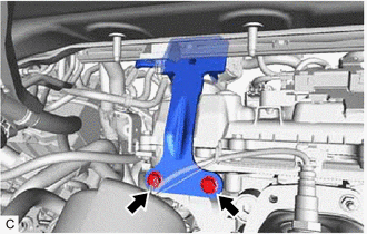
| (b) Remove the 2 bolts and fuel pump protector from the cylinder head sub-assembly. |
|
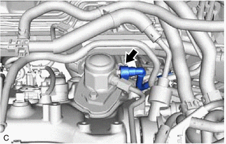
6. DISCONNECT NO. 2 FUEL TUBE SUB-ASSEMBLY
| (a) Disconnect the No. 2 fuel tube sub-assembly from the fuel pump assembly. Click here |
|
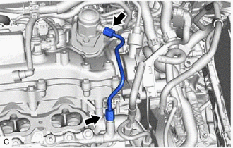
7. REMOVE NO. 1 FUEL PIPE SUB-ASSEMBLY
CAUTION:
To prevent serious injury due to fuel spray from the high-pressure fuel lines, always discharge fuel system pressure before removing any fuel system components.
| (a) Using a 17 mm union nut wrench, loosen the 2 union nuts of the No. 1 fuel pipe sub-assembly. |
|
| (b) Loosen the 2 bolts of the fuel pump assembly. |
|
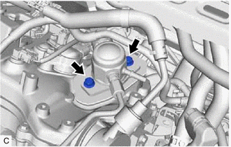
(c) Remove the No. 1 fuel pipe sub-assembly from the fuel delivery pipe RH and fuel pump assembly.
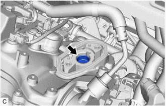
8. REMOVE FUEL PUMP ASSEMBLY
| (a) Disconnect the fuel pump assembly connector. |
|
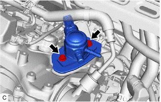
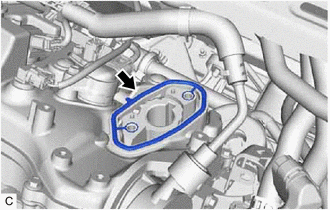
| (b) Remove the 2 bolts, fuel pump assembly and fuel pump lifter guide from the cylinder head cover sub-assembly. |
|
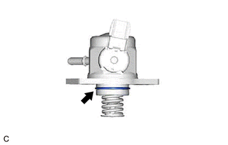
| (c) Remove the O-ring from the fuel pump assembly. |
|
| (d) Remove the fuel pump lifter assembly from the fuel pump lifter housing. |
|
| (e) Remove the fuel pump spacer gasket from the cylinder head cover sub-assembly. |
|
READ NEXT:
 Inspection
INSPECTION PROCEDURE 1. INSPECT FUEL PUMP ASSEMBLY (a) Measure the resistance according to the value(s) in the table below. Standard Resistance: Tester Connection Condition Specified Condit
Installation
INSTALLATION PROCEDURE 1. TEMPORARILY INSTALL FUEL PUMP ASSEMBLY (a) Turn the crankshaft pulley until the flat of the camshaft faces the fuel pump lifter assembly. HINT: This prevents the camshaft
SEE MORE:
MOST Communication Malfunction (B15D0)
DESCRIPTION Navigation system components communicate with each other via MOST communication. If a line short or short to ground occurs in a MOST communication line, communication will not be possible and the navigation system will not operate normally. After the engine switch is turned on (ACC), if
GVIF Disconnected (from EMV/MM Integrated Device to Multi Display) (B1575)
DESCRIPTION The radio receiver assembly and multi-display assembly are connected via video signal (digital) lines. This DTC is stored when a video signal (digital) line is disconnected. DTC No. Detection Item DTC Detection Condition Trouble Area B1575 GVIF Disconnected (from EMV/MM In
