Lexus ES: Removal
REMOVAL
CAUTION / NOTICE / HINT
The necessary procedures (adjustment, calibration, initialization or registration) that must be performed after parts are removed and installed, or replaced during knock control sensor removal/installation are shown below.
Necessary Procedures After Parts Removed/Installed/Replaced| Replaced Part or Performed Procedure | Necessary Procedure | Effect/Inoperative Function when Necessary Procedure not Performed | Link |
|---|---|---|---|
|
*: When performing learning using the Techstream.
Click here | |||
| Battery terminal is disconnected/reconnected | Perform steering sensor zero point calibration | Lane Control System (for Gasoline Model) | |
| Pre-collision System (for Gasoline Model) | |||
| Parking Support Brake System (for Gasoline Model)* | |||
| Lighting System (for Gasoline Model) | |||
| Memorize steering angle neutral point | Parking Assist Monitor System (for Gasoline Model) | | |
| Panoramic View Monitor System (for Gasoline Model) | | ||
| Initialize power trunk lid system | Power Trunk Lid System (for Gasoline Model) | | |
| Inspection after repair |
| |
NOTICE:
- After the engine switch is turned off, the radio receiver assembly records various types of memory and settings. As a result, after turning the engine switch off, make sure to wait at least 85 seconds before disconnecting the cable from the negative (-) battery terminal. (for Audio and Visual System)
- After the engine switch is turned off, the radio receiver assembly records various types of memory and settings. As a result, after turning the engine switch off, make sure to wait at least 85 seconds before disconnecting the cable from the negative (-) battery terminal. (for Navigation System)
PROCEDURE
1. REMOVE FUEL DELIVERY PIPE
Click here .gif)
2. REMOVE KNOCK CONTROL SENSOR
| (a) Disconnect the 2 knock control sensor connectors. |
|
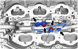
(b) Remove the 2 bolts and 2 knock control sensors from the cylinder block sub-assembly.
NOTICE:
If a knock control sensor has been struck or dropped, replace it.
READ NEXT:
 Inspection
INSPECTION PROCEDURE 1. INSPECT KNOCK CONTROL SENSOR (a) Measure the resistance according to the value(s) in the table below. Standard Resistance: Tester Connection Condition Specified Cond
Installation
INSTALLATION PROCEDURE 1. INSTALL KNOCK CONTROL SENSOR HINT: Perform "Inspection After Repair" after replacing a knock control sensor. Click here (a) Temporarily install the 2 knock control sensors
SEE MORE:
Abnormal Zero Point of Steering Angle Sensor (C1290)
DESCRIPTION The skid control ECU (brake booster with master cylinder assembly) acquires the steering angle sensor zero point every time the power switch on (READY) and the vehicle is driven at 35 km/h (22 mph) or more for approximately 5 seconds. The skid control ECU (brake booster with master cylin
Check Bus 3 Line for Short to +B
DESCRIPTION There may be a short circuit between one of the CAN bus lines and +B when there is no resistance between terminal 6 (CA3H) of the central gateway ECU (network gateway ECU) and terminal 16 (BAT) of the DLC3, or terminal 21 (CA3L) of the central gateway ECU (network gateway ECU) and termin
