Lexus ES: Installation
INSTALLATION
PROCEDURE
1. INSTALL KNOCK CONTROL SENSOR
HINT:
Perform "Inspection After Repair" after replacing a knock control sensor.
Click here .gif)
(a) Temporarily install the 2 knock control sensors to the cylinder block sub-assembly with the 2 bolts so that the knock control sensor installation position is as shown in the illustration.
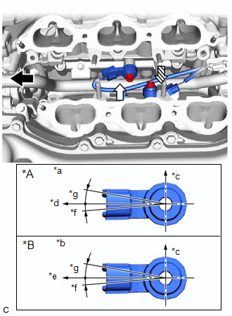
| *A | for Bank 1 |
| *B | for Bank 2 |
| *a | View A |
| *b | View B |
| *c | Top |
| *d | Engine Front |
| *e | Engine Rear |
| *f | 5° |
| *g | 10° |
.png) | Engine Front |
.png) | View A |
 | View B |
NOTICE:
- If a knock control sensor has been struck or dropped, replace it.
- Make sure that the knock control sensor is installed in the correct position.
| (b) Tighten the bolt (A). Torque: 20 N·m {204 kgf·cm, 15 ft·lbf} |
|
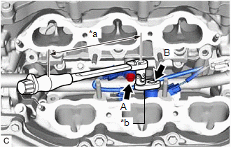
(c) Using a 10 mm union nut wrench, tighten the bolt (B).
Torque:
Specified tightening torque :
20 N·m {204 kgf·cm, 15 ft·lbf}
HINT:
-
Calculate the torque wrench reading when changing the fulcrum length of the torque wrench.
Click here
-
When using a 10 mm union nut wrench (fulcrum length of 22 mm (0.866 in.)) + torque wrench (fulcrum length of 162 mm (6.38 in.)):
17.6 N*m (179 kgf*cm, 13 ft.*lbf)
(d) Connect the 2 knock control sensor connectors.
2. INSTALL FUEL DELIVERY PIPE
Click here
3. PERFORM INITIALIZATION
(a) Perform "Inspection After Repair" after replacing a knock control sensor.
Click here
READ NEXT:
 Components
COMPONENTS ILLUSTRATION *1 MASS AIR FLOW METER SUB-ASSEMBLY - -
On-vehicle Inspection
ON-VEHICLE INSPECTION PROCEDURE 1. INSPECT MASS AIR FLOW METER SUB-ASSEMBLY HINT: Perform "Inspection After Repair" after replacing the mass air flow meter sub-assembly. Click here (a) Read the val
SEE MORE:
Brake Hold Operated Indicator Light Circuit
DESCRIPTION The brake hold operated indicator light illuminates when the brake hold system is operating (vehicle stopped via brake fluid pressure hold) and turns off when the brake hold system operation is finished (brake fluid pressure decreases). The brake hold system may not operate depending on
On-vehicle Inspection
ON-VEHICLE INSPECTION PROCEDURE 1. INSPECT GARAGE DOOR OPENER (a) Press each garage door opener ("HomeLink") switch and check that the ("HomeLink") indicator light turns on. If one or more of the garage door opener ("HomeLink") switches does not turn on the ("HomeLink") indicator light, check the
