Lexus ES: Suspension Control ECU Communication Stop Mode
DESCRIPTION
| Detection Item | Symptom | Trouble Area |
|---|---|---|
| Suspension Control ECU Communication Stop Mode | Any of the following conditions are met:
|
|
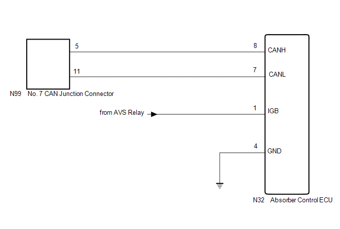
WIRING DIAGRAM
CAUTION / NOTICE / HINT
CAUTION:
When performing the confirmation driving pattern, obey all speed limits and traffic laws.
NOTICE:
-
Because the order of diagnosis is important to allow correct diagnosis, make sure to begin troubleshooting using How to Proceed with Troubleshooting when CAN communication system related DTCs are output.
Click here
.gif)
- Before measuring the resistance of the CAN bus, turn the engine switch off and leave the vehicle for 1 minute or more without operating the key or any switches, or opening or closing the doors. After that, disconnect the cable from the negative (-) battery terminal and leave the vehicle for 1 minute or more before measuring the resistance.
-
After turning the engine switch off, waiting time may be required before disconnecting the cable from the negative (-) battery terminal. Therefore, make sure to read the disconnecting the cable from the negative (-) battery terminal notices before proceeding with work.
Click here
-
After performing repairs, perform the DTC check procedure and confirm that the DTCs are not output again.
DTC check procedure: Turn the engine switch on (IG) and wait for 1 minute or more. Then operate the suspected malfunctioning system and drive the vehicle at 60 km/h (37 mph) or more for 5 minutes or more.
-
After the repair, perform the CAN bus check and check that all the ECUs and sensors connected to the CAN communication system are displayed as normal.
Click here
- Inspect the fuses for circuits related to this system before performing the following procedure.
HINT:
- Before disconnecting related connectors for inspection, push in on each connector body to check that the connector is not loose or disconnected.
- When a connector is disconnected, check that the terminals and connector body are not cracked, deformed or corroded.
PROCEDURE
| 1. | CHECK FOR OPEN IN CAN BUS LINES (ABSORBER CONTROL ECU BRANCH LINE) |
(a) Disconnect the cable from the negative (-) battery terminal.
| (b) Disconnect the N32 absorber control ECU connector. |
|
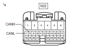
(c) Measure the resistance according to the value(s) in the table below.
Standard Resistance:
| Tester Connection | Condition | Specified Condition |
|---|---|---|
| N32-8 (CANH) - N32-7 (CANL) | Cable disconnected from negative (-) battery terminal | 54 to 69 Ω |
| NG | .gif) | REPAIR OR REPLACE CAN BRANCH LINES OR CONNECTOR (ABSORBER CONTROL ECU) |
|
.gif)
| 2. | CHECK HARNESS AND CONNECTOR (POWER SOURCE CIRCUIT) |
| (a) Measure the resistance according to the value(s) in the table below. Standard Resistance:
|
|
.png)
(b) Reconnect the cable to the negative (-) battery terminal.
| (c) Measure the voltage according to the value(s) in the table below. Standard Voltage:
|
|
.png)
| OK | | REPLACE ABSORBER CONTROL ECU |
| NG | | REPAIR OR REPLACE HARNESS OR CONNECTOR (POWER SOURCE CIRCUIT) |
READ NEXT:
 Center Airbag Sensor Communication Stop Mode
DESCRIPTION Detection Item Symptom Trouble Area Center Airbag Sensor Communication Stop Mode Any of the following conditions are met:
Communication stop for "Airbag" is indicated on th
Certification ECU Communication Stop Mode
DESCRIPTION Detection Item Symptom Trouble Area Certification ECU Communication Stop Mode Any of the following conditions are met:
Communication stop for "Certification (Smart)" is ind
Combination Meter ECU Communication Stop Mode
DESCRIPTION Detection Item Symptom Trouble Area Combination Meter ECU Communication Stop Mode Any of the following conditions are met:
Communication stop for "Combination Meter" is ind
SEE MORE:
Checking Monitor Status
CHECKING MONITOR STATUS The purpose of the monitor result (mode 06) is to allow access to the results of on-board diagnostic monitoring tests of specific components/systems that are not continuously monitored. Examples are catalysts and evaporative emissions (EVAP) systems. The monitor result allows
Software Incompatibility with Body Control Module Not Programmed (U032251)
DESCRIPTION If the forward recognition camera cannot verify the vehicle information sent from the main body ECU (multiplex network body ECU), the forward recognition camera stores DTC U032251. DTC No. Detection Item DTC Detection Condition Trouble Area MIL DTC Output from U032251
