
Lexus ES: Inspection
Lexus ES (XZ10) Service Manual / Engine & Hybrid System / 2gr-fks (engine Control) / Knock Sensor / Inspection
INSPECTION
PROCEDURE
1. INSPECT KNOCK CONTROL SENSOR
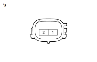
| (a) Measure the resistance according to the value(s) in the table below. Standard Resistance:
If the result is not as specified, replace the knock control sensor. |
|
READ NEXT:
 Installation
INSTALLATION PROCEDURE 1. INSTALL KNOCK CONTROL SENSOR HINT: Perform "Inspection After Repair" after replacing a knock control sensor. Click here (a) Temporarily install the 2 knock control sensors
Components
COMPONENTS ILLUSTRATION *1 MASS AIR FLOW METER SUB-ASSEMBLY - -
SEE MORE:
Installation
INSTALLATION PROCEDURE 1. INSTALL NO. 2 EXHAUST MANIFOLD HEAT INSULATOR (a) Type A: (1) Install the No. 2 exhaust manifold heat insulator to the exhaust manifold (TWC: Front Catalyst) with the 6 bolts. Torque: 11 N·m {112 kgf·cm, 8 ft·lbf} (b) Type B: (1) Install the No. 2 exhaust manifold heat
Tilt Position Sensor or Tilt Motor Circuit Component Internal Failure (B261096)
DESCRIPTION The tilt motor (steering column assembly) is operated by the power source voltage supplied from the multiplex tilt and telescopic ECU and tilts the steering column up and down. The tilt position sensor (Hall IC) in the tilt motor (steering column assembly) detects the tilt angle of the s
© 2016-2026 Copyright www.lexguide.net
