Lexus ES: Components
COMPONENTS
ILLUSTRATION
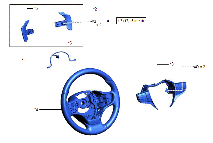
| *1 | NO. 1 SWITCH WIRE | *2 | SHIFT PADDLE SWITCH (TRANSMISSION SHIFT SWITCH ASSEMBLY) |
| *3 | STEERING PAD SWITCH ASSEMBLY | *4 | STEERING WHEEL ASSEMBLY |
| *5 | SHIFT PADDLE SWITCH LH (TRANSMISSION SHIFT SWITCH ASSEMBLY) | *6 | SHIFT PADDLE SWITCH RH (TRANSMISSION SHIFT SWITCH ASSEMBLY) |
.png) | N*m (kgf*cm, ft.*lbf): Specified torque | ● | Non-reusable part |
| ★ | Precoated part | - | - |
READ NEXT:
 Inspection
INSPECTION PROCEDURE 1. INSPECT SHIFT PADDLE SWITCH (TRANSMISSION SHIFT SWITCH ASSEMBLY) (a) Shift Paddle Switch LH (Transmission Shift Switch Assembly): (1) Measure the resistance according to the
Installation
INSTALLATION PROCEDURE 1. INSTALL NO. 1 SWITCH WIRE HINT: Perform this procedure only when replacement of the No. 1 switch wire is necessary. (a) Engage the 4 guides to install the No. 1 switch wir
Removal
REMOVAL CAUTION / NOTICE / HINT The necessary procedures (adjustment, calibration, initialization, or registration) that must be performed after parts are removed and installed, or replaced during shi
SEE MORE:
Freeze Frame Data
FREEZE FRAME DATA DESCRIPTION (a) Whenever a lane control system DTC is stored, the forward recognition camera stores the current vehicle state as Freeze Frame Data. CHECK FREEZE FRAME DATA (a) Connect the Techstream to the DLC3. (b) Turn the engine switch on (IG). (c) Turn the Techstream on. (d) En
Navigation Processor Malfunction (B15AD)
DESCRIPTION This DTC is stored when a malfunction occurs in the navigation ECU. DTC No. Detection Item DTC Detection Condition Trouble Area B15AD Navigation Processor Malfunction When either condition below is met:
A short to ground, short to +B or open occurs in the gyro signal
© 2016-2026 Copyright www.lexguide.net
