Lexus ES: Inspection
INSPECTION
PROCEDURE
1. INSPECT SHIFT PADDLE SWITCH (TRANSMISSION SHIFT SWITCH ASSEMBLY)
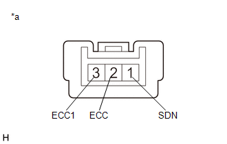
(a) Shift Paddle Switch LH (Transmission Shift Switch Assembly):
| (1) Measure the resistance according to the value(s) in the table below. Standard Resistance:
If the result is not as specified, replace the shift paddle switch LH (transmission shift switch assembly). |
|
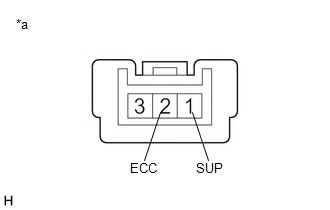
(b) Shift Paddle Switch RH (Transmission Shift Switch Assembly):
| (1) Measure the resistance according to the value(s) in the table below. Standard Resistance:
If the result is not as specified, replace the shift paddle switch RH (transmission shift switch assembly). |
|
READ NEXT:
 Installation
INSTALLATION PROCEDURE 1. INSTALL NO. 1 SWITCH WIRE HINT: Perform this procedure only when replacement of the No. 1 switch wire is necessary. (a) Engage the 4 guides to install the No. 1 switch wir
Removal
REMOVAL CAUTION / NOTICE / HINT The necessary procedures (adjustment, calibration, initialization, or registration) that must be performed after parts are removed and installed, or replaced during shi
SEE MORE:
CAN Communication Failure (Message Registry) (U1000)
DESCRIPTION This DTC is stored when the rear television camera assembly judges that it has an internal CAN malfunction. DTC No. Detection Item DTC Detection Condition Trouble Area U1000 CAN Communication Failure (Message Registry) Can communication failure (message registry) Rear
Installation
INSTALLATION CAUTION / NOTICE / HINT NOTICE: This procedure includes the installation of small-head bolts. Refer to Small-Head Bolts of Basic Repair Hint to identify the small-head bolts. Click here PROCEDURE 1. INSTALL ENGINE BALANCER ASSEMBLY Click here 2. INSTALL STIFFENING CRANKCASE ASSEM
