Lexus ES: Removal
REMOVAL
CAUTION / NOTICE / HINT
The necessary procedures (adjustment, calibration, initialization, or registration) that must be performed after parts are removed and installed, or replaced during shift paddle switch (transmission shift switch assembly) removal/installation are shown below.
Necessary Procedures After Parts Removed/Installed/Replaced| Replaced Part or Performed Procedure | Necessary Procedure | Effect/Inoperative Function when Necessary Procedure not Performed | Link |
|---|---|---|---|
|
*: When performing learning using the Techstream.
Click here | |||
| Auxiliary battery terminal is disconnected/reconnected | Perform steering sensor zero point calibration | Lane Control System (for HV Model) | |
| Pre-collision System (for HV Model) | |||
| Parking Support Brake System (for HV Model)* | |||
| Lighting System (for HV Model) | |||
| Memorize steering angle neutral point | Parking Assist Monitor System (for HV Model) | | |
| Panoramic View Monitor System (for HV Model) | | ||
| Initialize power trunk lid system | Power Trunk Lid System (for HV Model) | | |
NOTICE:
- Do not remove/install the spiral cable with sensor sub-assembly with the battery connected and the power switch on (IG).
- Do not rotate the spiral cable with sensor sub-assembly without the steering wheel assembly installed, with the auxiliary battery connected and the power switch on (IG).
- Ensure that the steering wheel assembly is installed and aligned straight when inspecting the steering sensor.
PROCEDURE
1. REMOVE STEERING WHEEL ASSEMBLY
Click here .gif)
2. REMOVE STEERING PAD SWITCH ASSEMBLY
Click here
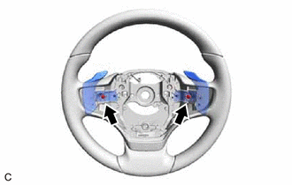
3. REMOVE SHIFT PADDLE SWITCH (TRANSMISSION SHIFT SWITCH ASSEMBLY)
| (a) Remove the 2 screws. |
|
| (b) Disengage the 4 claws. |
|
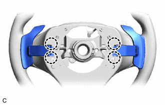
| (c) Disengage the 2 clamps to disconnect the 2 shift paddle switches (transmission shift switch assemblies) from the steering wheel assembly. |
|

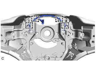
| (d) Disconnect the 2 shift paddle switch (transmission shift switch assembly) connectors to remove the 2 shift paddle switches (transmission shift switch assemblies) from the No. 1 switch wire. |
|

4. REMOVE NO. 1 SWITCH WIRE
HINT:
Perform this procedure only when replacement of the No. 1 switch wire is necessary.
| (a) Disengage the 4 guides and remove the No. 1 switch wire from the steering wheel assembly. |
|
READ NEXT:
 Adjustment
ADJUSTMENT PROCEDURE 1. SECURE VEHICLE (a) Fully apply the parking brake and chock a wheel. CAUTION:
Make sure to apply the parking brake and chock a wheel before performing this procedure.
If th
Components
COMPONENTS ILLUSTRATION *1 COOL AIR INTAKE DUCT SEAL *2 INLET AIR CLEANER ASSEMBLY *3 NO. 1 ENGINE COVER SUB-ASSEMBLY *4 AIR CLEANER ASSEMBLY WITH AIR CLEANER HOSE *5 FRONT L
SEE MORE:
Parts Location
PARTS LOCATION ILLUSTRATION *1 ECM *2 NO. 1 ENGINE ROOM RELAY BLOCK AND NO. 1 JUNCTION BLOCK ASSEMBLY - INJ FUSE *3 IGNITION COIL ASSEMBLY *4 SPARK PLUG
Fail-safe Chart
FAIL-SAFE CHART FAIL-SAFE CHART Adaptive Variable Suspension System DTC Chart Malfunction Item Fail-safe Operation C1715 C1716 C1717 Acceleration sensor circuit Partial control continues. C1731 C1732 C1733 C1734 Absorber control actuator circuit Control stops. C1781 Abso
